KROHNE IFC 090F Converter EEx-ATEX EN User Manual
Page 22
ALTOFLUX IFC 090 F-EEx and ALTOFLUX IFC 090 F / i-EEx
22
5.2
Replacement of electronics unit
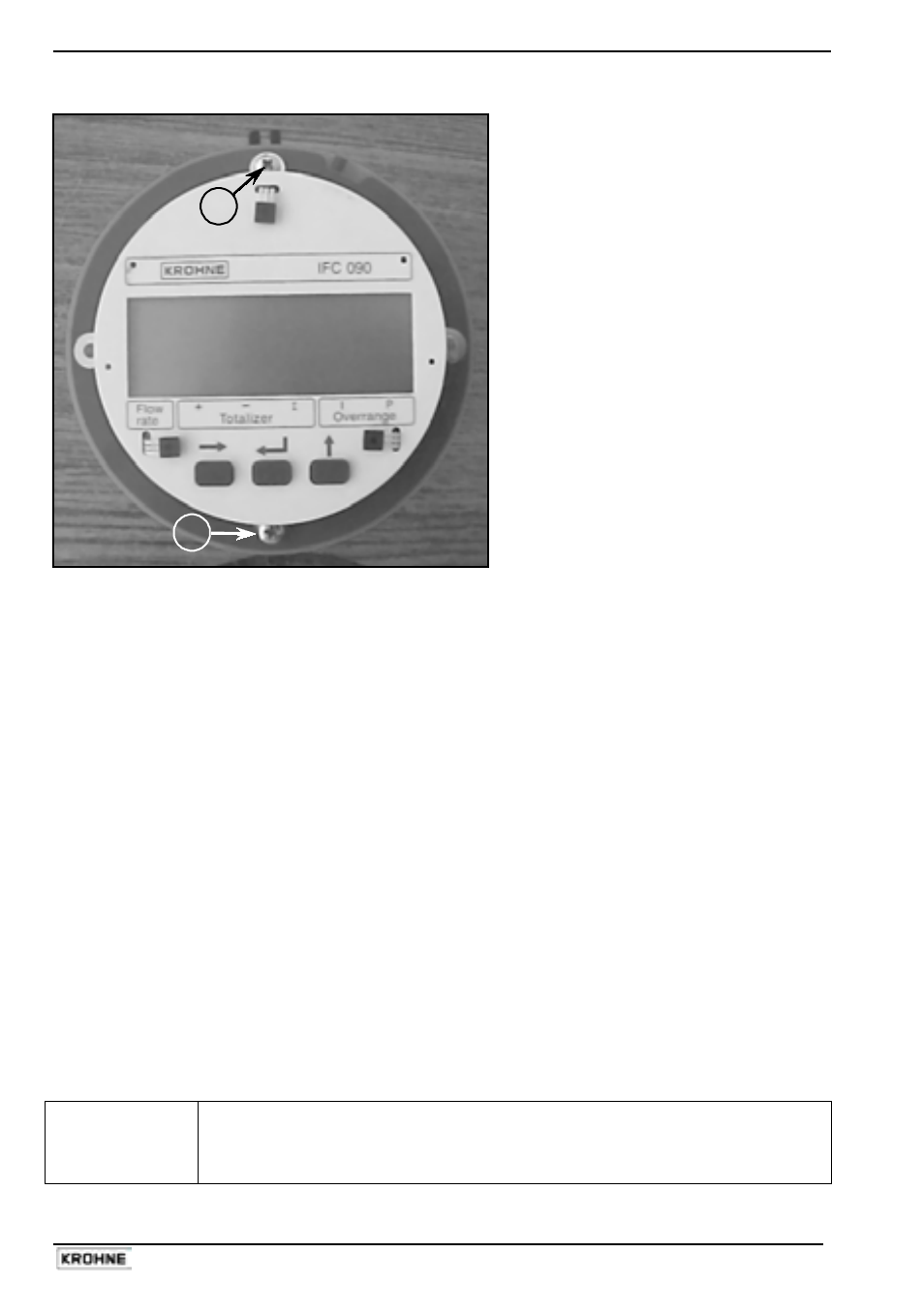
A
A
Display unit of IFC 090…-EEx
Refer to the standard Installation and
Operating Instructions for detailed
information about resetting and
reprogramming the new electronics unit
after replacement. The customer specific
data (like the value of the internal
totalizer) are stored in DATAPROM IC-
18, which must be transferred from the
"old" to the "new" electronics unit. See
Sect. 8.7 of the standard Installation and
Operating Instructions for detailed
information.
Before commencing work, note the instructions in Sect. 5.1, “Before opening".
Then continue as follows:
1.
Remove the display cover of the electronics compartment.
2.
Unscrew the two screws A (M3) of the display unit (see figure above) and turn it carefully
aside.
3.
Disconnect the 2-pole field circuit connector (item B in figure on last page) and the 3-pole
electrode circuit connector (item C). See figures in Sect. 5.1 and the following.
4.
Unscrew the two mounting screws D of the electronics unit and unscrew SE, which fixes
the copper ground strip to the back of the housing. A screwdriver with a long shaft (
≥ 200
mm) is most suitable for unscrewing screw SE (e.g. screwdriver type Philips No. 2).
5.
Carefully remove the electronics unit of the converter housing (see the remark below).
6.
Check if the voltage setting (only applicable for AC power supplies) and power fuse rating
are correct on the new electronics unit. If necessary, change the voltage setting or replace
the power fuse (see Sect. 5.3 and 5.4 of this manual).
7.
Carefully insert the electronics unit (keep cables aside, see remark below). Then mount the
unit completely into the housing and fix the screws. First the two screws D, then screw SE
and reconnect the 2-pole field circuit connector B and the 3-pole electrode circuit connector
C to the right counter-plugs on the electronics unit (see figure in Sect. 5.1).
8.
Finally screw the display unit back on the frame of the electronics via the two screws A.
9.
Screw the cover of the electronics compartment back into the housing.
Note the instructions of Sect. 5.1 ("After opening") during reassembling.
IMPORTANT !
Carefully keep the connecting cables of the field coil and electrode circuits to
the side of the housing, while removing respectively inserting the electronics
unit into the signal converter housing. This is to prevent damaging of the
connecting cables!