Electrical connections – KROHNE OPTISONIC 7300 Ex EN User Manual
Page 24
4
ELECTRICAL CONNECTIONS
24
OPTISONIC 7300 / 8300
www.krohne.com
05/2012 - 7312262200 - AD EX OPTISONIC 7300/8300 R02
The exact I/O-configuration for circuits A, B, C and D is order-specific and can be determined by
the CG36 number shown on the I/O sticker inside the terminal compartment. Therefore check
the data on the back of the GFC 300 electronics unit. The CG36 number contains 10 characters of
which the last three characters (XYZ) determine the configuration of the I/O circuits:
For schematic overviews of the CG36 numbers, refer to
Non-"Ex i" I/O connections
on page 25
and refer to
"Ex i" I/O connections
on page 27. These overviews do not show all details. The exact
connection diagram of a specific GFC 300 signal converter can be found on the sticker inside the
terminal compartment.
For use in gaseous hazardous areas:
For use in gaseous hazardous areas:
For use in gaseous hazardous areas:
For use in gaseous hazardous areas: The chosen cable glands must have the appropriate type of
protection for the terminal compartment that is increased safety (Ex e) or flameproof enclosure
(Ex d). They MUST be suitable for the conditions of use and correctly installed.
The flowmeter with the terminal compartment in type of protection increased safety “Ex e” is
factory supplied with two or three “Ex e” approved cable glands and one or no “Ex e” approved
blanking element (i.e. stopping plug).
The wiring of instruments has to be in accordance with the requirements as specified in the
relevant national or international standard for electrical installations in hazardous areas, e.g.
EN 60079-14. Section 9 (wiring systems) of this standard applies to all types of protection.
Section 10 (additional requirements for type of protection “d” - flameproof enclosures), section
11 (additional requirements for type of protection “e” - increased safety) and section 12
(additional requirements for type of protection “i” - intrinsic safety) apply to respectively “Ex d”,
“
Ex e” and “Ex i” performed connection (terminal) compartments.
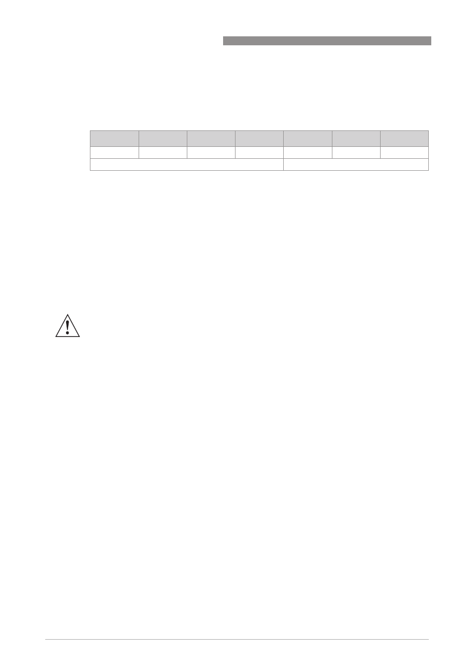
CG36
*
*
*
X
Y
Z
Pos 1...4
5
6
7
8
9
10
determine I/O circuits
WARNING!
The flowmeter with the terminal compartment performed as flameproof enclosure
“
Ex d
”
is
supplied with one
“
Ex d
”
approved stopping plug and two temporary plugs. The temporary plugs
are only intended for sealing the housing against entry of dust, moisture or else during
transport, handling and storage. These temporary plugs must be replaced by suitable
“
Ex d
”
approved cable glands, stopping plugs or conduit adapters with sealing devices before the
flowmeter is put into operation. Unused openings must be sealed by suitable certified plugs.