Figure 7. rkw 600w power failure timing diagram, Load connection, 1 connecting the load using local sensing – KEPCO RKW 600W Series Operator Manual User Manual
Page 11: 2 connecting the load using remote sensing, Load connection 5.1, Connecting the load using local sensing, Connecting the load using remote sensing, Rkw 600w power failure timing diagram, Correct and incorrect methods of load connection, Re 8)
RKW 600W 060110
9
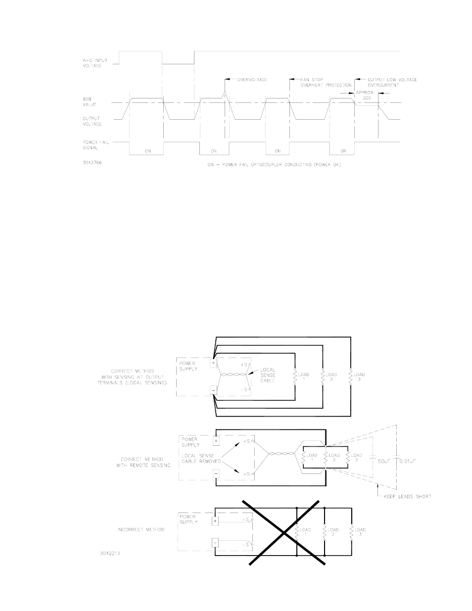
FIGURE 7. RKW 600W POWER FAILURE TIMING DIAGRAM
5.
LOAD CONNECTION
5.1
CONNECTING THE LOAD USING LOCAL SENSING
To connect the load for local sensing, the local sensing cable supplied must be installed to con-
nect the +S terminal with DC Output (+), and –S terminal with DC Output (–). The load is con-
nected across DC output (+) and (–) (see Figure 8).
5.2
CONNECTING THE LOAD USING REMOTE SENSING
For remote sensing the load is connected as shown in Figure 8. Remote error sensing at the load
terminals compensates for voltage drop in the connecting wires as indicated in Table 2. For
remote sensing, the local sensing cable must be removed from the ±S and ±DC Output terminals.
NOTE: If the overvoltage protection trips too easily, install one external electrolytic capacitor, rated
470µF min. between the +DC Output and +S terminals and one between the –DC Output and –S
terminals.
FIGURE 8. CORRECT AND INCORRECT METHODS OF LOAD CONNECTION