KEPCO RA 76 User Manual
Page 3
6/20/03
228-1439 REV 1
3
1. INSTALLATION
The Rack Adapter is equipped with handles; while installation is proceeding, the Rack Adapter must be supported
from below until it has been secured. The Rack Adapter can also be fitted with optional slides (see Figure 7).
1. To activate the front panel pilot lights, the pilot light resistors must be configured to match the FAW output volt-
age prior to installing the power supplies. The front panel must be partially disassembled to facilitate the inser-
tion of resistors matched to the associated power supply output voltage. Figure 6 illustrates the schematic.
Figure 5 illustrates component location. Proceed as follows:
a. Remove the top cover of the rack adapter by removing screws from the top (six for RA 75 and nine for RA
76) and one from the top center of the front panel above Test Point 1 (–).
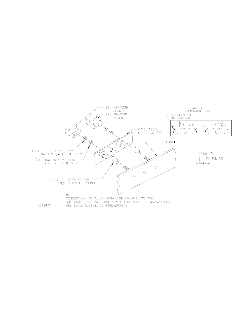
b. Separate the front panel from the chassis by removing 5 screws from the front panel, then disassemble
the PCB assembly (see Figure 5) by removing two 6-32 X 1/4 ACF. ST. nuts (P/N 102-0004), associated
washers (P/N 103-0015) and spacers (P/N 104-0227).
FIGURE 5. FRONT PANEL DISASSEMBLY FOR INSERTION OF PILOT LIGHT RESISTORS