B.94 [source:]current:[:level]mode? query, B.95 diag:ext command, B.96 diag:ext ? query – KEPCO Kit 219-0439, 219-0440, 219-0441, ATE-DMG External Control Kit User Manual
Page 4: Figure 3. schematic diagram, Curr:mode, Diag:ext, B.94 [source:]current:[:level]mode, Query, B.96 diag:ext, Or 03
4
228-1469 REV 3
022305
KEPCO, INC.
G 131-38 SANFORD AVENUE G FLUSHING, NY. 11352 U.S.A. G TEL (718) 461-7000 G FAX (718) 767-1102
http://www.kepcopower.com
G email: [email protected]
B.94
[SOURce:]CURRent:[:LEVel]MODE?
QUERY
CURR:MODE?
Syntax:
Short Form: [SOUR:]CURR[:LEV]:MODE?
Long Form: [SOURce:]CURRent[:LEVel]MODE]?
Return Value: FIXED or EXTERNAL
Description: Returns FIXED or EXTERNAL whether current control is from the keypad or GPIB interface (FIXED) or from
an external analog reference voltage (EXTERNAL).
B.95
DIAG:EXT
COMMAND
DIAG:EXT
Syntax:
Short Form: DIAG:EXT
Long Form: DIAG:EXT
where
HEX
Description: DIAG:EXT 01 initializes external analog control and 03 sets VOLT:MODE and CURR:MODE to EXTERNAL
DIAG:EXT 00 turns off the external analog control feature). Setting is stored in NVRAM and retained upon sub-
sequent power up.
B.96
DIAG:EXT
?
QUERY
DIAG:EXT?
Syntax:
Short Form: DIAG:EXT?
Long Form: DIAG:EXT]?
Return Value: 00
HEX
, 01
HEX
or 03
HEX
Description: Returns 00 when external analog control feature is disabled. Returns 01 when external analog control fea-
ture is enabled. Returns 03 when external analog control feature is enabled upon power up.
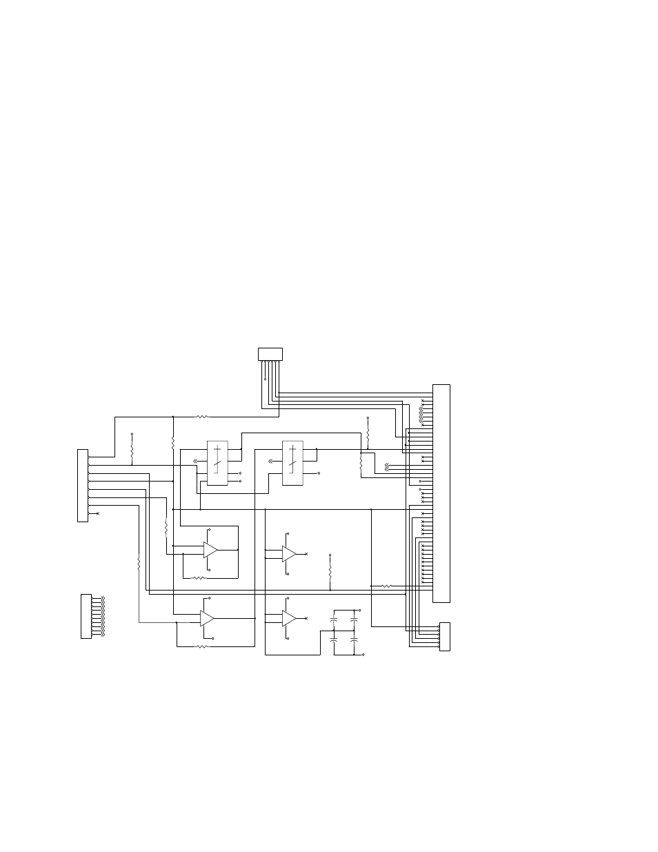
FIGURE 3. SCHEMATIC DIAGRAM
M15V
M15V
P15V
M
15V
P15V
P15V
M15V
M15V
P15V
P15V
P15V
M15V
M15V
M15V
P15V
P15V
P15V
P15V
P15V
A+
B+
B-
A-
V_EXT
C_EXT
Aout
Bout
A-
V_EXT
Aout
B-
B+
A+
C_EXT
Bout
COMMON
COMMON
C_INT
C_INT
LAG NETWORK
V_INT
V_INT
GND
VOLTAGE 0 - 6V
COMMON
INT/EXT
MODE
GND
GND
GND
GND
CURRENT 0 - 1V
MODE
GND
CMMD CURRENT 0 - 10V
GND
GND
CMMD VOLTAGE 0 - 10V
GN
D
GND
GND
R10
10K
R9
10K
R1
Note 1
R6
1K
R7
10K
R8
13K
R5
Note 5
+
-
U2B
LM324
5
6
7
4
11
A11 J3
CONVERSION
1
2
3
4
5
6
R11
Note 3
A11 J4
PAIRED ATE
1
2
3
4
5
6
R4
Note 4
R3
10K
+
-
U2C
LM324
10
9
8
4
11
+
-
U2D
LM324
12
13
14
4
11
U1B
DG 390A
9
5
10
6
8
13
11
14
S1
S2
SEL
D2
D1
GND
V+
V-
U1A
DG 390A
16
4
15
3
1
12
S1
S2
SEL
D2
D1
(Vl)
A11 J1
1
2
3
4
5
6
7
8
9
10
11
12
13
14
15
16
17
18
19
20
21
22
23
24
25
26
27
28
29
30
31
32
33
34
35
36
37
38
39
40
41
42
43
44
45
46
47
48
49
50
+
-
U2A
LM324
3
2
1
4
11
C3
.1
C1
.1
C4
.1
C5
.1
A11 J5
EXT_CMD
1
2
3
4
5
6
7
8
9
10
R2
Note 1
A11 J2
To A7
1
2
3
4
5
6
7
8
MODEL R2 R1
6-100 Not installed JUMPER
15-50 6980 11000
25-40 5620 18200
36-30 6980 35700
55-20 4220 35700
75-15 7870 90900
100-10 5760 90900
150-7 4220 100000
NOTES
1. Values for R1 and R2 are model specific
2. All Resistance in ohms.
3. Jumper Installed DMG option.
4. Jumper Installed for standard ATE or SN
option.
5. Jumper Installed for standard ATE.
6. Resistors R1,R2, R4, R6, R7, R8 installed
for DMG option.
7. For Standard ATE and SN option, external jumpers
should be installed between:
J5 P3-P4
J5 P9-P10
J4 P5-P6
8. For SLOW mode jumper should be installed between
J3 P1-P2
9. For FAST mode jumpers should be installed between
J3 P3-P4
J3 P5-P6
and jumper J3 P1-P2 should be removed.
10. For PAIRED units, remove jumper J4 P5-P6