Figure 1. digital board a7 prom location, Figure 2. adapter assembly a11, component location – KEPCO Kit 219-0439, 219-0440, 219-0441, ATE-DMG External Control Kit User Manual
Page 2
2
228-1469 REV 3
022305
KEPCO, INC.
G 131-38 SANFORD AVENUE G FLUSHING, NY. 11352 U.S.A. G TEL (718) 461-7000 G FAX (718) 767-1102
http://www.kepcopower.com
G email: [email protected]
7.
Reclose the IC tube. Remove wrist strap and disconnect it from the ATE-DMG chassis.
8.
Proceed to PAR. 2.4 to replace the Adapter Assembly
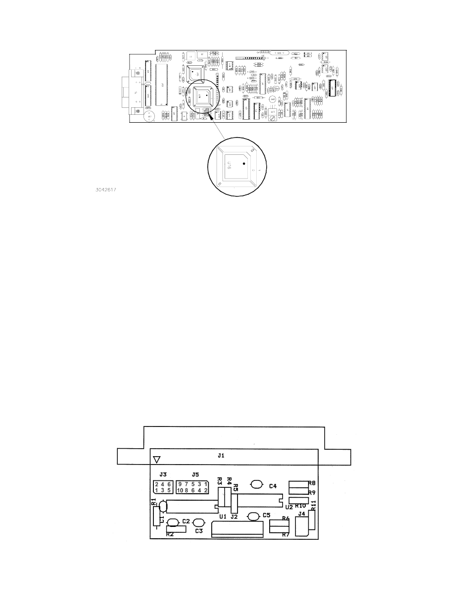
FIGURE 1. DIGITAL BOARD A7 PROM LOCATION
CAUTION:FAILURE TO USE THE ESD WRIST STRAP MAY DAMAGE THE PROM!
2.4 ADAPTER ASSEMBLY A11 REPLACEMENT PROCEDURE (SEE FIGURE 2)
NOTE: See PAR. 2.2 for disassembly.
1.
Unplug interconnecting cable going to A7J1 from A11 Assembly.
2.
Remove and discard A11 assembly and interconnecting cable assembly.
3.
Install new A11 Assembly and connect new interconnecting cable from A11J2 to A7J1.
2.5 REASSEMBLY
1.
Attach the cover to the chassis using 20 screws.
2.
Install the power cord and connect the unit to source power, then proceed to PAR. 2.6 to initialize and calibrate the unit.
2.6 INITIALIZATION AND CALIBRATION
1.
Turn on power supply. The unit will initialize with ENTER PS TYPE displayed on the LCD.
2.
Use the keypad to enter the voltage followed by the current (e.g., for the ATE 25-40DMG, enter 2540), then press ENTER
(refer to Table 4-1 in ATE-DMG Service Manual).
3.
The unit must then be calibrated by following the prompts displayed on the LCD (see Table 4-1 of ATE-DMG Service Man-
ual).
FIGURE 2. ADAPTER ASSEMBLY A11, COMPONENT LOCATION