Iv — operation, Parallel operation, Figure 4. load connections – KEPCO KDN 24V Series Operator Manual User Manual
Page 4: Figure 5. parallel connections (kdn 24-20 only)
4
228-1674 REV 2
050813
KEPCO, INC. " 131-38 SANFORD AVENUE " FLUSHING, NY. 11355 U.S.A. " TEL (718) 461-7000 " FAX (718) 767-1102
http://www.kepcopower.com " email: [email protected]
the AC input Neutral, Line and Ground wires to the respec-
tive terminals of the terminal block (see Figure 1). Wire strip
length for both a-c and d-c connector is approximately 1/4
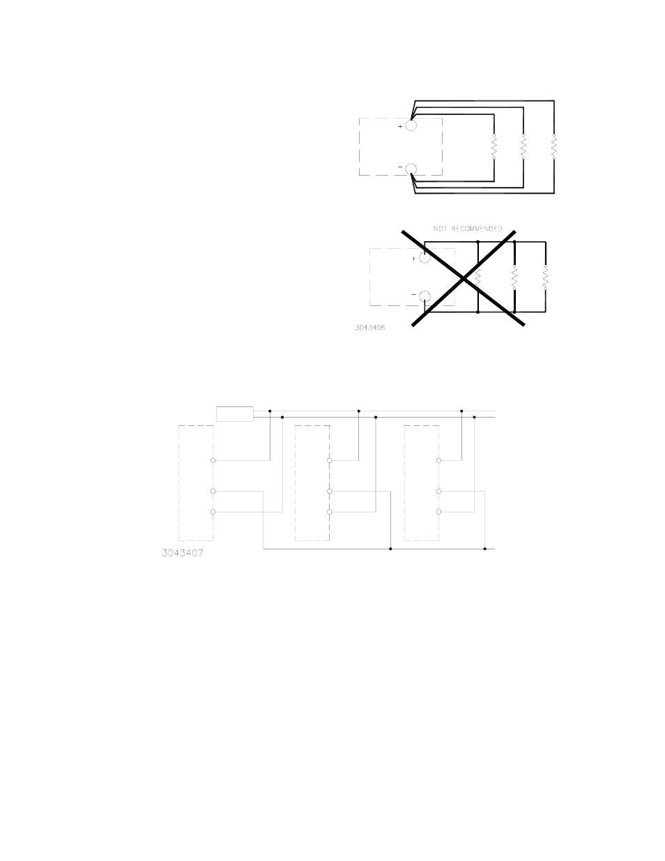
inch (6 - 7mm). See Figure 4 for connecting multiple loads.
IV — OPERATION
The Output Voltage Adjust trimmer (see Figure 1) allows
adjustment of the output voltage within the range specified in
Table 1. When output voltage is within specified adjustment
range, the green LED is on. The LED is off as described in
“Power OK Indicator:” on page 2.
PARALLEL OPERATION:
Model KDN 24-20 (only) may
be operated in parallel for increased current capability (see
Figure 5). Connecting the PS (Power Share) terminals forces
the current load to be shared equally among paralleled units.
FIGURE 4. LOAD CONNECTIONS
FIGURE 5. PARALLEL CONNECTIONS (KDN 24-20 ONLY)
A
B
CORRECT METHOD
POWER
SUPPLY
POWER
SUPPLY
LOAD
1
LOAD
2
LOAD
3
LOAD
1
LOAD
2
LOAD
3
PS
+
-
KDN
KDN
-
+
PS
-
+
PS
KDN
LOAD
NOTE: ISOLATION DIODES ARE INCLUDED IN KDN 24-20.