Figure 1. component locations, Figure 2. output power vs. temperature, Iii — installation/removal – KEPCO KDN 24V Series Operator Manual User Manual
Page 3: Mounting on din rail, Removal, Figure 3. power supply mounting, Connections
KEPCO, INC. " 131-38 SANFORD AVENUE " FLUSHING, NY. 11355 U.S.A. " TEL (718) 461-7000 " FAX (718) 767-1102
http://www.kepcopower.com " email: [email protected]
050813
228-1674 REV 2
3
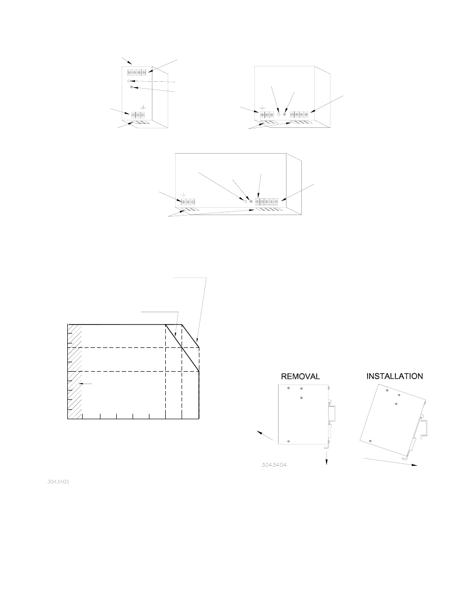
FIGURE 1. COMPONENT LOCATIONS
FIGURE 2. OUTPUT POWER VS. TEMPERATURE
III — INSTALLATION/REMOVAL
MOUNTING ON DIN RAIL.
The KDN Series is
designed to mount on a 35mm DIN rail only as shown in Fig-
ure 3 with ventilation holes at top and bottom. Install by insert-
ing one edge of mounting bracket on DIN rail as shown, then
press down to snap onto DIN rail.
REMOVAL.
Remove by pulling hook down to release
mounting bracket from DIN rail, then swing power supply away
from DIN rail.
.
FIGURE 3. POWER SUPPLY MOUNTING
CONNECTIONS.
Connect the load to the power supply d-c
output + + and – – terminals shown in Figure 1. The AC input
power is applied via the terminal block. Make sure to connect
OUTPUT
VOLTAGE
ADJUST
PWR
OK
INSERT
WIRES
+
+
AC
INPUT
-
-
INSERT
WIRES
- -
+ +
PWR
OK
OUTPUT
VOLTAGE
ADJUST
AC
INPUT
POWER
SHARE
AC
INPUT
- -
+ +
PWR OK
OUTPUT
VOLTAGE
ADJUST
INSERT
WIRES
INSERT
WIRES
DC
OUTPUT
DC
OUTPUT
DC
OUTPUT
3043403
N L
L N
L
N
KDN 24-5
KDN 24-10
KDN 24-20
Ambient Temperature (°C)
-10
0
10
20
30
40
50
60
70
10
20
30
40
50
60
75
90
100
O
ut
pu
t P
ow
er
R
at
in
g
(%
)
KDN 24-5 (115V A-C AND 230V A-C),
KDN 24-10 (115V A-C AND 230V A-C),
KDN 24-20 (230V A-C)
KDN 24-20 (115V A-C)
NOTE: Operation from -10°C to 0°C is as follows:
KDN 24-5: Yes, normal operation
KDN 24-10: No
KDN 24-20: Start up at -10°C, nominal line voltage only.
SEE NOTE.