Iv — specifications (c, t, x, y), Input, Stabilization – KEPCO HSF-PFC 100W Series Operator Manual User Manual
Page 6
6
228-1533 REV 15
083013
KEPCO, INC. 131-38 SANFORD AVENUE FLUSHING, NY. 11355 U.S.A. TEL (718) 461-7000 FAX (718) 767-1102
http://www.kepcopower.com email: [email protected]
IV — SPECIFICATIONS (C, T, X, Y)
The following specifications apply to all HSF-PFCC,
PFCT, PFCX, and PFCY (suffix C, T, X, Y) 100 Watt
Series models. Table 2 lists the specifications that differ
for each model. Common specifications that apply to all
suffix C, T, X, Y models are listed in the paragraphs follow-
ing Table 2.
NOTE: Specifications apply to all models except where
otherwise indicated.
INPUT:
Voltage:
Nominal:120V a-c/240V a-c;
Range:
90-264V a-c;
125-370V d-c. (polarity insensitive)
Frequency: Nominal 50-60 Hz; Range 47-440Hz
(From 66 to 440Hz leakage current may exceed
UL/VDE safety spec. limit)
Current (nominal output at rated load):
1.5A a-c max
@100-120V a-c rms
1.1A max for 3.3V model
0.75A a-c max @200-240V a-c rms
0.55A max for 3.3V model
Initial Turn-on Surge: cold start 25 °C (First surge
only, not including the current flow into the EMI fil-
ter):
14A typ. (100 V a-c, 100% load)
28A typ. (200 Va-c, 100% load)
Power Factor: 0.99 typ. @100V a-c;
0.92 typ. @ 200V a-c.
Switching Frequency:
160KHz typical
STABILIZATION:
Source Effect (full load):
Range 90-132V a-c or 170 -264V a-c,
0.1% typ.; 0.2% max.
3.3V model: 5mV typ., 10mV max.
Load Effect (10% to 100% load change):
0.5% typ.; 1.5% max.
3.3V, 5V models: 1.5% typ., 2.0% max.
Temperature Effect: Range -10° to 71°C
0.5% typ.; 1.0% max.
Combined Effect (includes source, load, and
temperature effects):
0.9% typ.; 1.8% max.
Time Effect (1/2 hr-8 hr at 25
o
C):
0.2% typ.; 0.5% max.
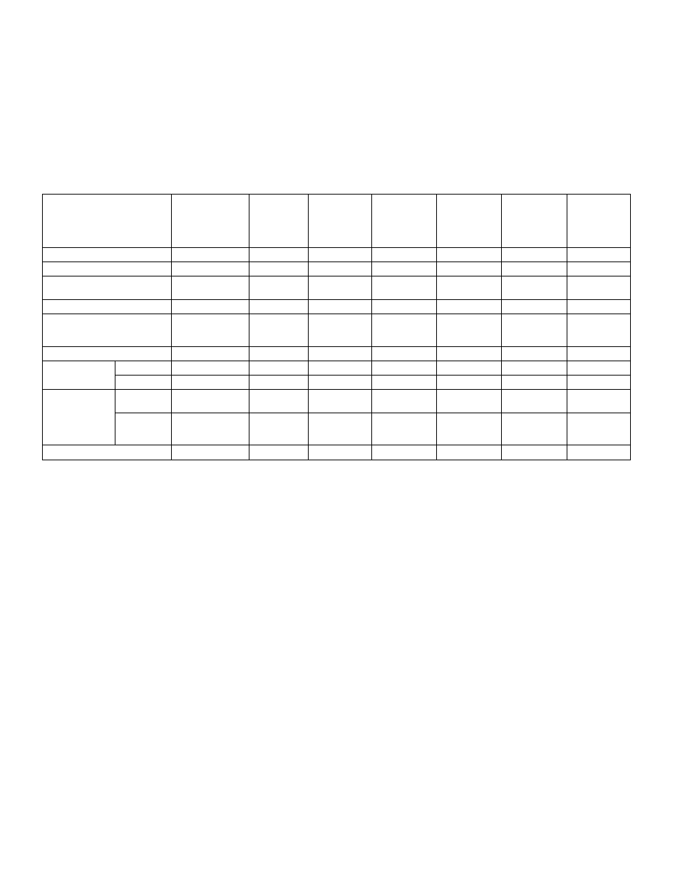
TABLE 2. OUTPUT RATINGS AND SPECIFICATIONS, HSF-PFC 100W SERIES (SUFFIX C, T, X, Y ONLY)
MODEL
HSF 3.3-25
(1) (2) (7)
PFCC
PFCT
PFCX
PFCY
HSF 5-20
(1)
PFCC
PFCT
PFCX
PFCY
HSF12-8.4
(1)
PFCC
PFCT
PFCX
PFCY
HSF 15-6.7
(1)
PFCC
PFCT
PFCX
PFCY
HSF 24-4.2
(1)
PFCC
PFCT
PFCX
PFCY
HSF 28-3.5
(1)
PFCC
PFCT
PFCX
PFCY
HSF 48-2
(1)
PFCC
PFCT
PFCX
PFCY
OUTPUT VOLTS, d-c (NOMINAL)
3.3V
5V
12V
15V
24V
28V
48V
ADJUSTMENT RANGE
2.8 - 3.5V
4.3 - 5.3V
11.4 - 12.6V
13.5 - 16.5V
19.2 - 26.0V
26.5 - 29.5V
44.0 - 52.0V
OVERVOLTAGE SETTING
(25 °C, Nom. Input)
3.75 - 4.7V
5.6 - 6.4V
13.3 - 15.4V
16.8 - 18.8V
26.5 - 30.0V
29.7 - 34.7V
54.5 - 59.5V
OUTPUT CURRENT (NOMINAL)
(3)
25A
(3)
20A
8.4A
6.7A
4.2A
3.5A
2A
CURRENT LIMIT SETTING
w(25 °C, Nom. Input)
Rectangular type characteristic
26.2A min.
21.0A min.
8.82A min.
7.03A min.
4.68A min.
3.8A min.
2.2A min.
OUTPUT POWER (MAXIMUM)
(4)
82.5W
100W
100.8W
100.5W
100.8W
100.8W
100.8W
EFFICIENCY (typ.)
100 Va-c
79%
83%
84%
85%
85%
85%
86%
240 Va-c
81%
85%
86%
87%
87%
87%
88%
RIPPLE AND
NOISE
(5)
(mV p-p)
0-40°C,
10-100% load
switching
(max)
80
80
100
100
150
150
200
spike noise
(max)
(d-c—50MHz)
120
120
150
150
200
200
300
Sense Resistor Value (milliohms)
(6)
5
5
10
20
20
30
50
(1) Unless otherwise noted, specifications are identical for all options.
(2) Forced current Share not available for 3.3V Models.
(3) Derates same as Output Power.
(4) See power rating curve, Figure 3.
(5) Ripple and noise will be approximately 1.5 times higher when
operating temperature range is between –10°C to 0°C.
(6) Sense resistor on C and Y Models used for current monitoring. See
“Current Monitor.” on page 2 for details.
(7) Natural convection cooled; see Figure 4.