Figure 4. dip switch configuration, 2 front panel access, Dip switch configuration – KEPCO HSF 600W Series (no suffix, suffix C) Operator Manuals User Manual
Page 9: Re 4), Standard and c models, Detail view
HSF 600W 022713
7
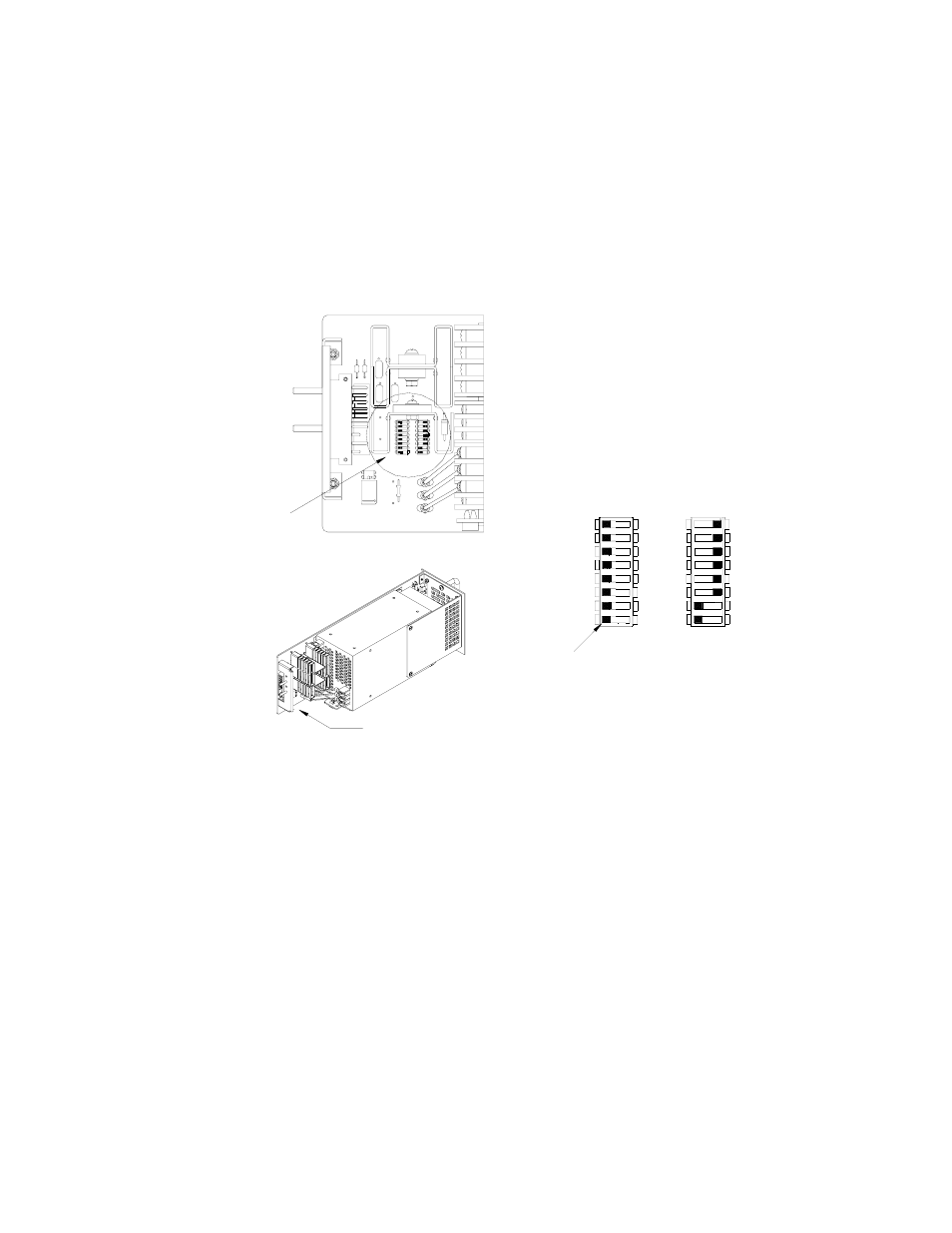
• Positions 3 and 4 either allow the front panel reset button to be used to reset the unit
after a fault or allow Remote on-off via mechanical switch or logic level (see PAR. 3.5).
• Positions 5 and 6 allows alarm signals to be produced from either internal relay, Form C
contacts (one NO, one NC) or open-collector logical alarm signals (see PAR. 3.7.2).
• For standard or C models position 8 of SW1 either disables (default) or enables the
visual alarm indication (see PAR. 3.7.1).
FIGURE 4. DIP SWITCH CONFIGURATION
3.2
FRONT PANEL ACCESS.
The front panel provides a power ON/OFF switch controlling input power and a "VDC ON" indica-
tor which lights green when the unit is operating. If the unit is connected in a parallel configuration,
the indicator lights red if the unit shuts off automatically, or the POWER switch is set to OFF.
CAUTION: DO NOT repeatedly toggle the power ON/OFF switch as this may cause unit to
fault.
NOTE: The ON/OFF switch must be set to OFF before removing unit from rack adapter.
If remote on-off is not enabled (see PAR. 3.5), the OUTPUT RESET button restores output power
in the event that overcurrent or overvoltage protection has tripped, or thermal overload or fan mal-
function has occurred.
If remote voltage control (see PAR. 3.4.2) is not enabled, the front panel Vadj trimmer (see PAR.
3.4.1) provides adjustment of the output voltage within the limits specified in Table 2; test points
are available at the front panel for monitoring the DC output.
3043031
SEE DETAIL VIEW
SEE APPLICABLE
DESCRIPTION
FOR STANDARD
OR C MODELS.
NOTE: NOT ALL COMPONENTS SHOWN.
DETAIL VIEW
SW2 SW1
REF
1
1
REF
-NOT USED
ALARM LED DISABLE
SW1
SW2
+PF
-COM
N/A
-PF
+RC
-RC
RV
+PF
5
5
7
8
6
7
8
-PF
6
3
4
2
3 +RC
-RC
4
RV
2
FACTORY DEFAULT SETTING:
- FRONT PANEL VADJ CONTROL
- RELAY ALARM SELECTED
- VISUAL ALARM DISABLED
- REMOTE ON-OFF DISABLED
Standard and C Models
ON
OFF
OFF
ON
6
6
8
7
8
7
3
5
4
1
2
3
4
5
1
2
TAB
- SN 488-B SN 488-D JQE 1/4 Rack Series KLP Series User Manual, Rev 2 KLP Series User Manual, Rev 4 KLP Series User Manual KFD 15-10-28W KFD 6-25-28W KFD 6-25-60W KFD 15-10-60W KFD 24-4.2-28W JQE Full Rack Series BHK-MG VISA Driver Manual (Both Full and 1/2 Rack) ABC VISA INSTRUMENT DRIVER ATE-DMG SERIES HSF 300W Series (no suffix) Operator Manuals