3 keying, 4 output voltage control, 1 front panel voltage control – KEPCO HSF 600W Series (no suffix, suffix C) Operator Manuals User Manual
Page 10: Front panel controls, indicators and test points, R. 3.4.1), R 3.4)
8
HSF 600W 022713
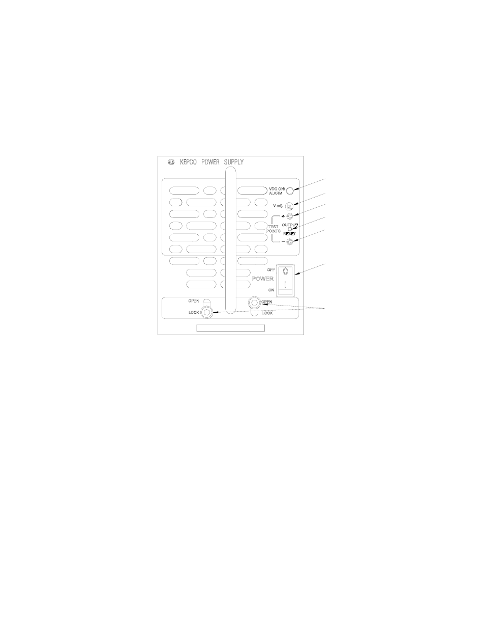
Figure 5 shows the location of all operating controls, indicators and test points followed by an
explanation of each.
3.3
KEYING
Keying of the HSF 600W is established at the factory. The output voltage determines which key
pins are installed (see Figure 3, Detail A). When the proper holes in the rack adapter are blocked
by keying screws installed by the user, only a power supply of the correct voltage can be inserted
in the rack adapter slot. Refer to the RA 19-4C Manual for rack adapter keying instructions.
1. VDC ON/ALARM indicator. Lights green when unit is operating. Can be configured by DIP
switch to light red to indicate loss of output voltage in parallel configurations.
2. V.ADJ Output voltage adjustment trimmer: Adjusts output voltage within limits specified in
Table 2 (see PAR. 3.4.1). Not functional if remote voltage control is enabled (see PAR.
3.4.2).
3. DC output test points (+, –): Connect to voltmeter to monitor output voltage.
4. OUTPUT RESET switch. Used to recycle power in the event of an alarm condition (see PAR.
3.6). Not functional when remote on/off control is enabled (see PAR. 3.5).
5. POWER ON/OFF switch. Applies power to the unit. CAUTION: Power must be OFF before
unit is removed from the rack adapter.
6. Retaining Latches (2). Prevents inadvertent removal of unit from rack adapter (see PAR.
FIGURE 5. FRONT PANEL CONTROLS, INDICATORS AND TEST POINTS
3.4
OUTPUT VOLTAGE CONTROL
Output Voltage can be controlled from either the front panel (PAR. 3.4.1) or externally using a
trimpot or voltage source (PAR. 3.4.2).
3.4.1 FRONT PANEL VOLTAGE CONTROL
Output voltage can be manually adjusted with the voltage adjustment control, Vadj (see Figure 5
for location) when DIP switches SW1 and SW2 (see Figure 4 for location) are configured as
3042857
1
2
3
4
3
5
6
- SN 488-B SN 488-D JQE 1/4 Rack Series KLP Series User Manual, Rev 2 KLP Series User Manual, Rev 4 KLP Series User Manual KFD 15-10-28W KFD 6-25-28W KFD 6-25-60W KFD 15-10-60W KFD 24-4.2-28W JQE Full Rack Series BHK-MG VISA Driver Manual (Both Full and 1/2 Rack) ABC VISA INSTRUMENT DRIVER ATE-DMG SERIES HSF 300W Series (no suffix) Operator Manuals