KEPCO CS 06 Chassis Slides (for EL Series Electronic Load) User Manual
Page 3
061711
228-1734 REV 1
3
KEPCO, INC. 131-38 SANFORD AVENUE FLUSHING, NY. 11355 U.S.A. TEL (718) 461-7000 FAX (718) 767-1102
http://www.kepcopower.com email: [email protected]
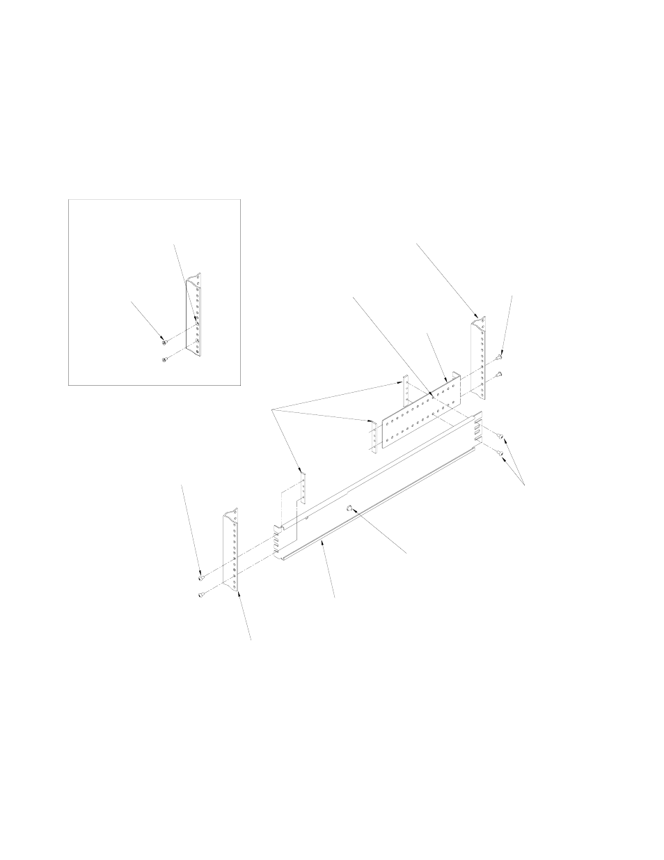
3. Attach two end brackets to the two cabinet sections of slides using four screws and two bar nuts (see Figure
3). Use appropriate holes to accommodate cabinet.
4. Attach two front cabinet rails to two cabinet sections using four pan head screws and two bar nuts. For flush
mounting use four flat head screws instead of the pan head screws.
5. Attach two rear cabinet rails to two cabinet sections using four pan head screws and two bar nuts.
FIGURE 3. ATTACHING END BRACKETS AND CABINET MOUNTING RAILS TO CABINET SECTION
CABINET MOUNTING RAIL,
REAR, LEFT SIDE
(NOT SUPPLIED)
MACHINE SCREW (3),
10-32 x 3/8 PH
PAN HEAD
END
BRACKET
0.31 IN. CLEARANCE REQUIRED
BEHIND CABINET SECTION TO
ALLOW LOCK BUTTON TO RELEASE.
CABINET
SECTION
BAR NUT
CABINET MOUNTING RAIL
FRONT, LEFT SIDE
(NOT SUPPLIED)
FOR FLUSH MOUNTING,
SEE DETAIL
MACHINE SCREW (3),
10-32 x 1/2 PH
PAN HEAD
3043548
MACHINE SCREW (2),
10-32 x 3/8 PH
PAN HEAD
MACHINE SCREW (2),
10-32 x 1/2 PH
FLAT HEAD
COUNTERSINK HOLES
OF CABINET MOUNTING
RAIL FOR FLUSH MOUNTING
FLUSH MOUNTING
USE APPROPRIATE HOLES
TO ACCOMMODATE CABINET