Rj-45 twisted pair port pinouts, Figure 48. rj-45 connector and port pin layout – Allied Telesis Layer 3 Gigabit Ethernet Switch x600-24Ts-POE User Manual
Page 104
Appendix A: Technical Specifications
104
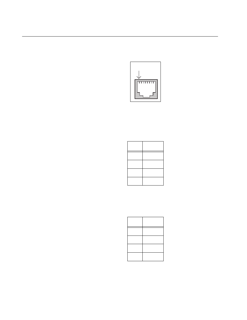
RJ-45 Twisted Pair Port Pinouts
Figure 48 illustrates the pin layout of an RJ-45 connector and port.
Figure 48. RJ-45 Connector and Port Pin Layout
Table 14 lists the pin signal definitions when a port is operating in the MDI
configuration at 10 or 100 Mbps.
Table 15 lists the pin signal definitions when a port is operating in the MDI-
X configuration at 10 or 100 Mbps.
The MDI/MDI-X setting is established automatically when a port is set to
Auto-Negotiation. If a port’s speed and duplex are set manually, the MDI/
MDI-X setting defaults to the MDI-X setting.
Table 14. MDI Pin Signals - 10 or 100 Mbps
Pin
Signal
1
TX+
2
TX-
3
RX+
6
RX-
Table 15. MDI-X Pin Signals - 10 or 100 Mbps
Pin
Signal
1
RX+
2
RX-
3
TX+
6
TX-
Pin 1
This manual is related to the following products: