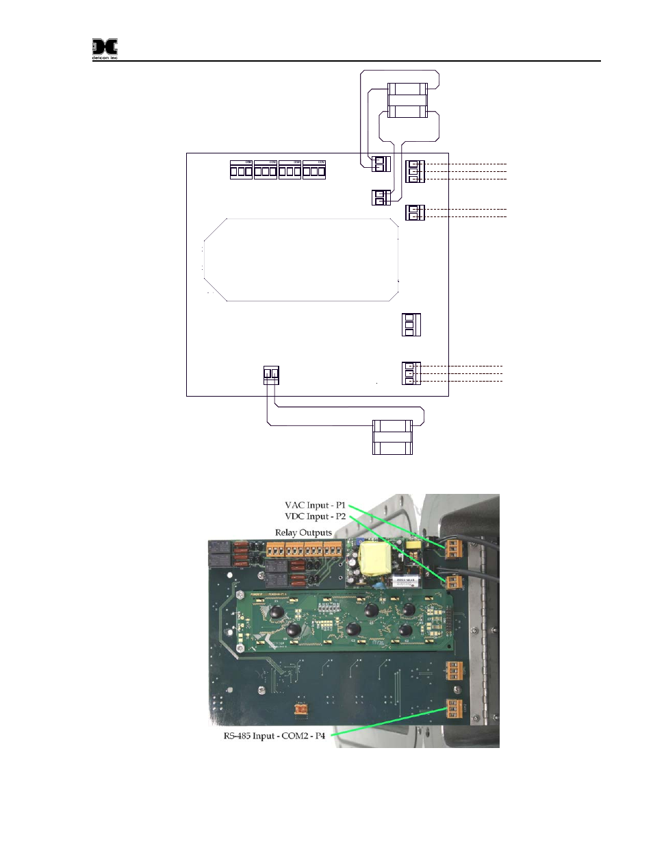
Figure 2 wiring diagram, Figure 3 controller pcb connections, Figure 3 – Detcon RD-8X User Manual
Page 7: Inals at p1labeled “vac in” (refer to figure 3), Figure 3). this input can
RD-8X-N4X Operators Manual
CONTROLLER PCA
FAULT ALARM3 ALARM2 ALARM1
VD
C
IN
CO
M 1
CO
M 2
AC
V
IN
+
L1
L2
E
A
B
S
A
B
S
NC NO
NC NO
NC NO
NC NO
120VAC (L1)
Neutral (L2)
RESET SWITCH
1
2
SW1
Yel 18AWG
Yel 18AWG
Power Switch
1
2
SW2
3
4
Ground
VDC - (Return)
VDC + (11.5~30VDC)
RS-485 - B
RS-485 - A
RS-485 Shield
RESET
P5
P5
P5
P2
P11
P1
P10
P9
P8
P7
P6
Wiring
Customer
Supplied
Wiring
Customer
Supplied
Figure 2 Wiring Diagram
Figure 3 Controller PCB Connections
Model RD-8X-N4X Operator Manual
Rev. 1.0
Page 3 of 14
See also other documents in the category Detcon Equipment:
- 12B (16 pages)
- FL-10 (7 pages)
- 10C Facilities (18 pages)
- 10C (29 pages)
- 10B (10 pages)
- 1212-N4X (9 pages)
- 812-N4X (9 pages)
- 1212B (5 pages)
- 612B (5 pages)
- 1610-N4X (28 pages)
- 1010-N4X (14 pages)
- 610-N4X (12 pages)
- 1610-N1 (4 pages)
- 810-N1-24VDC (10 pages)
- 410-N1-24VDC (4 pages)
- MCX-32-N1P (55 pages)
- RD-64X-N4X (41 pages)
- 880RA-N4X (36 pages)
- 880RA-N4X (23 pages)
- 880A-N1R (45 pages)
- 880A-N4X (50 pages)
- 880A-N4X (43 pages)
- X40-08-N4X (70 pages)
- 240 (33 pages)
- SW-AV1-N4 (12 pages)
- SW-AV2-DV1 (12 pages)
- A1V1 (9 pages)
- RXT-300 (47 pages)
- RXT-320 (31 pages)
- CXT-N4X (28 pages)
- SW-HMI-32-N4X (24 pages)
- SW-V1-DV2 (11 pages)
- SW-AV1-DV1 (14 pages)
- SW-AV2-DV2 (12 pages)
- SW-AV1-DV2 (12 pages)
- SmartWireless CX (33 pages)
- SmartWireless CXT (49 pages)
- CX-IR (38 pages)
- CX-DM (44 pages)
- CXT-IR (48 pages)
- CXT-DM (56 pages)
- P-1000 (28 pages)
- 1000 (32 pages)
- 1000_CO2 (32 pages)
- 1000_H2S (34 pages)