Detcon RD-8X User Manual
Page 12
RD-8X-N4X Operators Manual
3 **
16
2
3
4 **
16
3
4
5 **
16
4
5
6 **
16
5
6
7 **
16
6
7
8 **
16
7
8
9 **
16
8
9
10 **
16
9
10
11 **
16
10
11
12 **
16
11
12
13 **
16
12
13
14 **
16
13
14
15 **
16
14
15
16 **
16
15
16
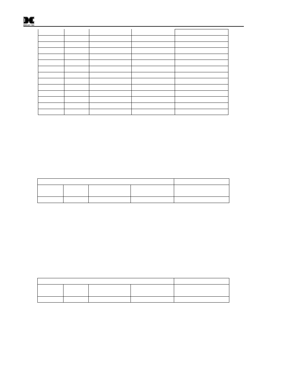
**- R
epresent the modbus address of the remote device. The slave ID for each channel enabled on the RD-
8X must match the modbus address of the remote device. Failure to assign the proper slave ID will result
in a “COMM ERROR” for the corresponding channel.
NOTE: The number of activated channels can be less than (but not greater than) the controller’s
maximum input capacity. The maximum input capacity is 16 channels.
4.3.2 Model RD-8X to Model 10X / 12X
Table 2
RD-8X: Setup Channel Data
Model 10X / 12 X
Channel
Slave ID
Register to Read
Reading Register
Channel
* **
6
1
1
* - Represents RD-8X channel the remote device will be assigned to.
** - Represents the modbus address of the remote device. The slave ID for each channel enabled on the
RD-8X must match the modbus address of the remote device. Failure to assign the proper slave ID will
result in a “COMM ERROR” for the corresponding channel.
NOTE: The number of activated channels can be less than (but not greater than) the controller’s
maximum input capacity. The maximum input capacity is 16 channels.
4.3.3 Model RD-8X to Model 140
Table 3
RD-8X: Setup Channel Data
Model 140
Channel Slave ID
Register to Read
Reading Register
Channel
* **
7
0
***
* - Represents RD-8X channel the remote device will be assigned to.
Model RD-8X-N4X Operator Manual
Rev. 1.0
Page 8 of 14