Detcon 972-071170-0LC User Manual
Page 6
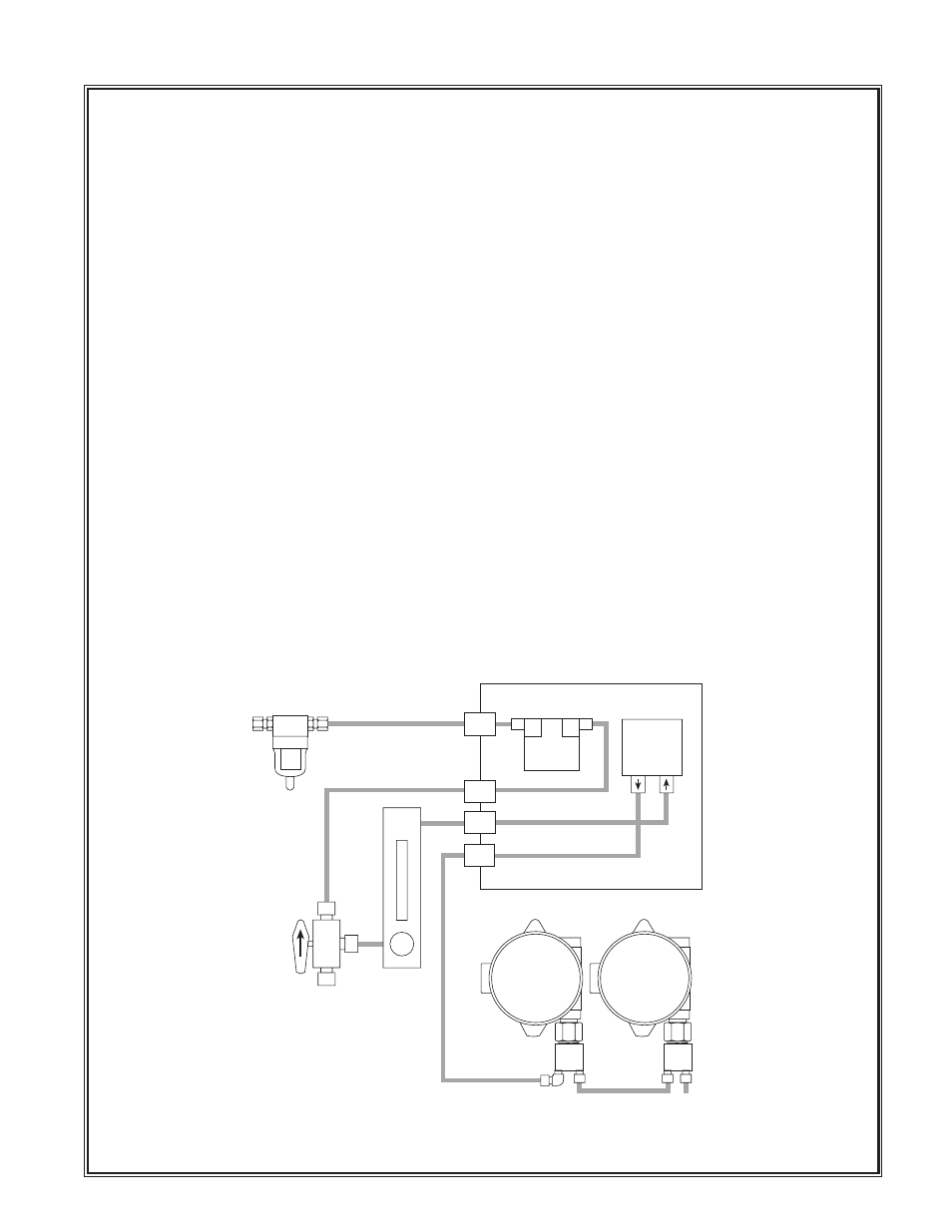
To Calibrate: (refer to illustration on the previous page)
1. Turn the 3-way valve so that the arrow is pointing down. Sample is now being drawn from the CAL port.
2. Using the 1/4" Tee assembly, connect the span gas cylinder to the calibration port. Note that the cylinder
flow rate should be 1000 ml/m while the sample draw flow rate should be adjusted to 500 ml/m. This will
assure that the sample is not diluted. Be sure to ad the 6” vent tubing as shown to prevent dilution.
3. Follow the calibration instructions given in the sensor instruction manual.
4. Close cylinder valve to allow clearing/zero stability. Note that zero and span functions may interact
slightly with one another. Zero and span tests may be repeated 2 or 3 times as necessary.
5. When calibration is complete turn the 3-way valve so that the arrow is pointing up.
1.5 SPARE PARTS
Part#
Description
3254 & 3254-BT2
Power switch (need both parts)
2831-G
Power indicator lamp
2831-R
Flow fualt indicator lamp
5151-02
Flow fault circuit assembly
3518
24 VDC pump
3489
1000 ml/m flow meter with valve
3606-SD1/SD2
117VAC to 24VDC power supply assembly
8236
Moisture filter pot
1.6 WARRANTY
Detcon Inc., as manufacturer, warrants under intended normal use each new Model 972-07117-0LC gas
detection system to be free from defects in material and workmanship for a period of one year from the
date of shipment to the original purchaser. Sensor assembly warranties are explained in their respective
instruction manuals. All warranties and service policies are FOB the Detcon Inc. facility located in The
Woodlands, Texas.
Detcon Model 972-071170-0LC Gas Detection System PG.6
Sample
Moisture Filter
CAL
Flow
Meter
Set
500-1000
ml/m
VENT
SENSOR #1
P1
P2
PUMP
Flow
Switch
SENSOR #2