Flow fault circuit, Flow fault contacts, 2 start up – Detcon 972-071170-0LC User Manual
Page 4: 3 flow fault detection
1.2 START UP
Upon completion of all tubing connections and field wiring turn on the power switch located on the enclo-
sure door. Note that the power lamp illuminates. If applicable, note that the sensor LCD indicators activate.
Varying readings may occur during sensor warm-up. Allow approximately 1 hour to stabilize (24 hours is best).
Also note air flow through the flow meter. Adjust the flow meter as necessary so that it falls between 500
and 1000 ml/m (milli liters per minute).
Assure that all field tubing connections are secure by obstructing the end of the sample line and observ-
ing that the flow meter decreases to “0” flow.
1.3 FLOW FAULT DETECTION
Flow fault detection consists of a flow fault circuit assembly located inside the enclosure and a door mount-
ed fault indicator lamp. If the air flow falls below a predetermined set point the following will occur: the
flow fault alarm relays will energize; an LED indicator mounted on the flow fault PCB will illuminate; the
door mounted flow fault lamp will illuminate; the 4-20mA signal will be opened via relay #1 on the flow
fault circuit board (this will allow for flow fault programming at the remote recording device or computer.
Because the pressure inside the sample and vent flow tubing differs according to the tubing length , the
flow fault circuit will require calibration after installation.
To calibrate the flow fault circuit, first determine at what point it is desired that the flow fault circuit is
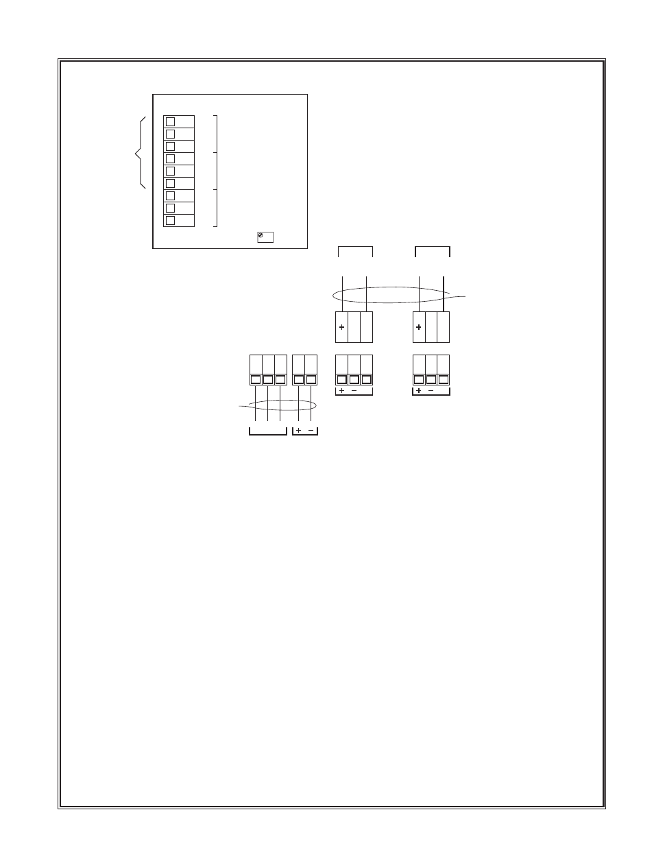
Detcon Model 972-071170-0LC Gas Detection System PG.4
P7
P6
P5
L1 L2 GND
mA
117 VAC
IN
24 VDC
IN
Battery
Backup
SENSOR #1
Flow
Fault
Circuit
COM
NO
NC
1
COM
NO
NC
2
COM
NO
NC
3
PT1
mA
Signal
Loop
Wire signal loop to controllers
“+” to “Sensor +” on controller
“mA” to “Sensor mA” on controller
Wire 117 VAC & optional 24 VDC
backup to the lugless connectors.
Two discreet form C dry contacts
are provided (2 & 3) by the flow
fault circuit for alarm devices. The
first set of contacts (1) are
prewired to interrupt the 4-20mA
signal output in the event of a
flow fault. This will allow for flow
fault monitoring at any
controller/computer that the signal
is wired in to.
P7
mA
SENSOR #2
mA
Signal
Loop
FLOW
FAULT
CONTACTS