3 electrical connections – Detcon 1000_H2S User Manual
Page 13
Model 1000 H2S Echem
Model 1000 H2S Echem Instruction Manual
Rev. 2.8
Page 9 of 30
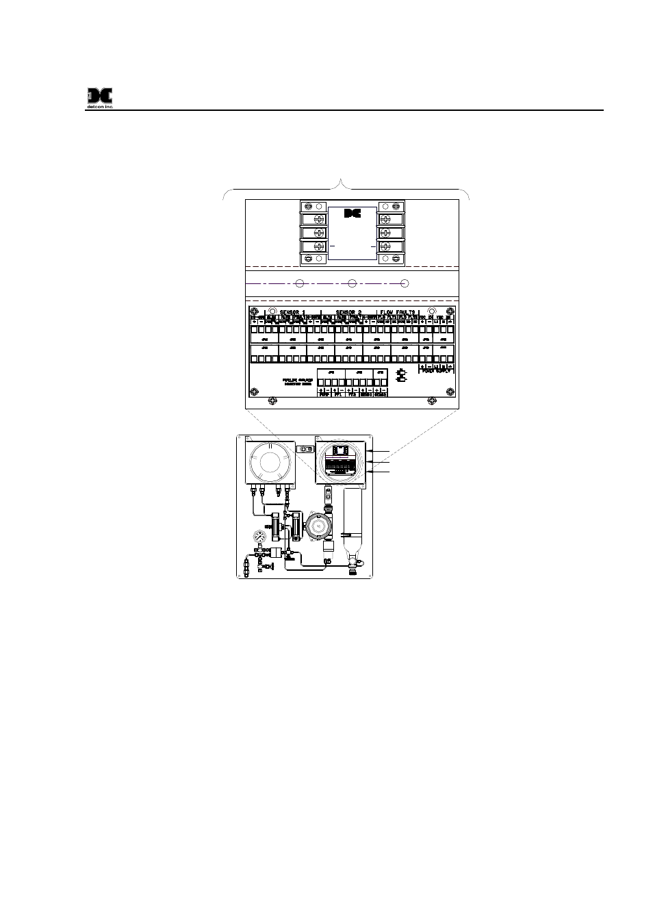
3.3 Electrical Connections
AIR
FLOW
SAMPLE
FLOW
+
+
24VDC
OUT
2.1A
18-36
VDC
IN
+
+
24VDC
OUT
2.1A
18-36
VDC
IN
+
+
24VDC
OUT
2.1A
18-36
VDC
IN
4-20mA, RS485,
Alarm/Fault Sensor Relays
Low Flow Air/ Sample Relays
(Optional)
117VAC / 24VDC In
Customer Connections
+24VDC
-24VDC
(Ground)
INPUT
+
-
Figure 10 Installation Wiring Connections
1. For AC powered unit connect 117/220VAC to the terminal connector labeled “VAC IN” ( JP8A) inside
the explosion-proof enclosure on the upper right.
If applicable, connect 24VDC to the Terminal
Connector Board labeled “VDC IN” (JP7A) (See Figure 10.)
2. The 4-20mA and/or RS-485 signal outputs should be wired from the terminal PCB and then out the right
side of the “Power Supply” explosion-proof enclosure (Figure 10).
3. Discrete alarm relay contacts are provided for three alarms: Fault, Low and High. The contacts consist of
common and choice of normally open or normally closed.
Contact output selections are jumper
programmable on the sensor connector board. See DM-624 wiring diagram for details. These connections
also should be wired out of the right side of the “Power Supply” explosion-proof enclosure. (Figure 10).
4. Optional Low Flow Fault alarms for Sample gas and Air are available. They provide a form “C” relay
contact (common, normally open and normally closed) rated 1 amp at 30VDC/0.24 amp at 125VAC.
Relay contacts are pre-wired to the I/O connector PCB located in the “Power Supply” explosion-proof
enclosure and are labeled “FLO FLT1” and “FLO FLT2” respectively (Figure 10).