Figure 5 calibration setup, Figure5 calibration setup, Houston,texas – Detcon 971-071170-0DL User Manual
Page 9
Model 971-071170-0DL
Note:
It is critical that air dilution be set in coordination with the entry value for AutoSpan.
The air dilution used during span calibration must be maintained as a constant or calibration
will drift. If air dilution ratio is changed, span calibration must be repeated.
detcon, inc.
HOUSTON,TEXAS
SAMPLE DRAW
GAS DETECTION SYSTEM
CAL PORT
SET
AIR
FLOW
SET
SAMPLE
FLOW
SAMPLE
PORT
0
50
100
150
200
250
0
0.4
0.8
1.2
1.6
2.0
1.0
0.2
0.6
1.4
1.8
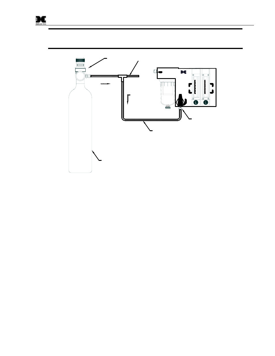
Fixed Flow
Regulator
6" of vent tube
CALIBRATION
PORT
Teflon tubing
Span Gas
Cylinder
1000
ml/min
500 ml/min
Figure5 Calibration setup
Required material:
1. Span gas cylinder containing gas as per instructions in the sensor instruction manual.
2. 1/4" Tee tubing fitting as shown in
To Calibrate: (refer to Figure5)
1) Turn the 3-way valve so that the arrow is pointing down. Sample is now being drawn from the CAL port.
2) a) Using the 1/4" Tee assembly, connect the span gas cylinder to the calibration port. Note that the
cylinder flow rate should be 1000 ml/m while the sample draw flow rate should be adjusted from 100- 500
ml/m. This will assure that the sample is not diluted. Be sure to add the 6” vent tubing as shown to
prevent dilution.
b) Make sure air dilution flow is set to target level according to customer’s requirement.
3) Follow the calibration instructions given in the sensor instruction manual.
4) Close cylinder valve to allow clearing/zero stability. Note that zero and span functions may interact
slightly with one another. Zero and span tests may be repeated 2 or 3 times as necessary.
5) When calibration is complete turn the 3-way valve so that the arrow is pointing up.
971-071170-0DL Instruction Manual
Rev. 0.0
Page 5 of 8