Electrical connections, Relays and rs 485 setup, Figure 4 customer wiring diagram – Detcon 971-071170-0DL User Manual
Page 7: 3 electrical connections, 4 relays and rs 485 setup
Model 971-071170-0DL
Note:
Observe correct polarity when terminating all input/output wiring. Failure to do so
may result in circuit damage on power up. See the field wiring diagram below for terminal
locations.
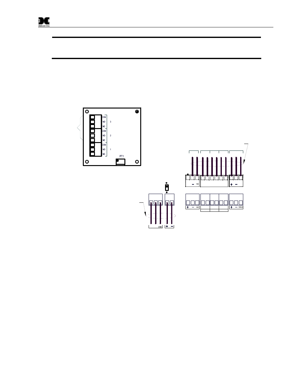
2.3 Electrical connections
1. Connect 117VAC to the connector labeled “117VAC IN”.
2. If applicable, connect 24 VDC battery backup to the connector labeled “24 VDC IN”.
3. If applicable, connect a remote recording device or computer to the 4-20 mA signal output connector.
The terminals are labeled SENSOR “–” and “mA”.
FLOW
FAULT
CIRCUIT
Two discrete form C dry contacts
are provided (set 2 and 3) by the
flow fault circuit for alarm devices.
The first set of contacts (1) are
pre-wired to interrupt the 4-20 mA
signal output in the event of a
"flow fault". This will allow for
flow fault monitoring at any
controller / computer that the
signal is wired to.
L1
L 2
117 VAC
IN
24 VDC
IN
Battery
Backup
SENSOR #1
FAULT
ALARM 1 ALARM 2
C
NO/NC
C
NO/NC
C
NO/NC
RS-485 #1
P6
P5
D1
P9
P8
P7
J2
J1
SH
LD
NO
/N
C
COM
NO
/N
C
COM
NO
/N
C
COM
RS-485 #1
4-20
mA
FLT ALM 1
ALM 2
Wire alarms and the 4-20mA output
signal to the plug connectors
FLOW
FAULT
CONTACTS
Wire 117VAC & optional
24 VDC backup to the
designated connectors
ALARM CONTACTS #1
Figure 4 Customer wiring diagram
2.4 Relays and RS 485 Setup
1. If applicable, connect alarm devices. Discrete alarm relay contacts are provided for three alarms:
Fault, Low, and High. The contacts consist of common and choice of normally open or normally
closed. Contact output selections are jumper programmable on the sensor connector board. See the
sensor manual for contact ratings and other information.
2. If applicable, connect flow fault alarm wiring. Two sets of form C contacts (common, normally open
and normally closed) are provided. Relay contacts are rated 1 amp at 30VDC/.24 amp at 125VDC.
3. If applicable, connect RS-485 wiring. The RS-485 requires 24 gauge, two conductor, shielded,
twisted pair cable between sensor and host PC. Use Belden part number 9841. Two sets of terminals
are located on the connector board to facilitate serial loop wiring from sensor to sensor. Wiring
designators are +, –, and shield.
971-071170-0DL Instruction Manual
Rev. 0.0
Page 3 of 8