Operation, Figure 8 typical unit wiring, 0 operation – Detcon SW-V1-DV2 User Manual
Page 10
SW-V1-DV2
SW-V1-DV2 Instruction Manual
Rev.0.0
Page 6 of 7
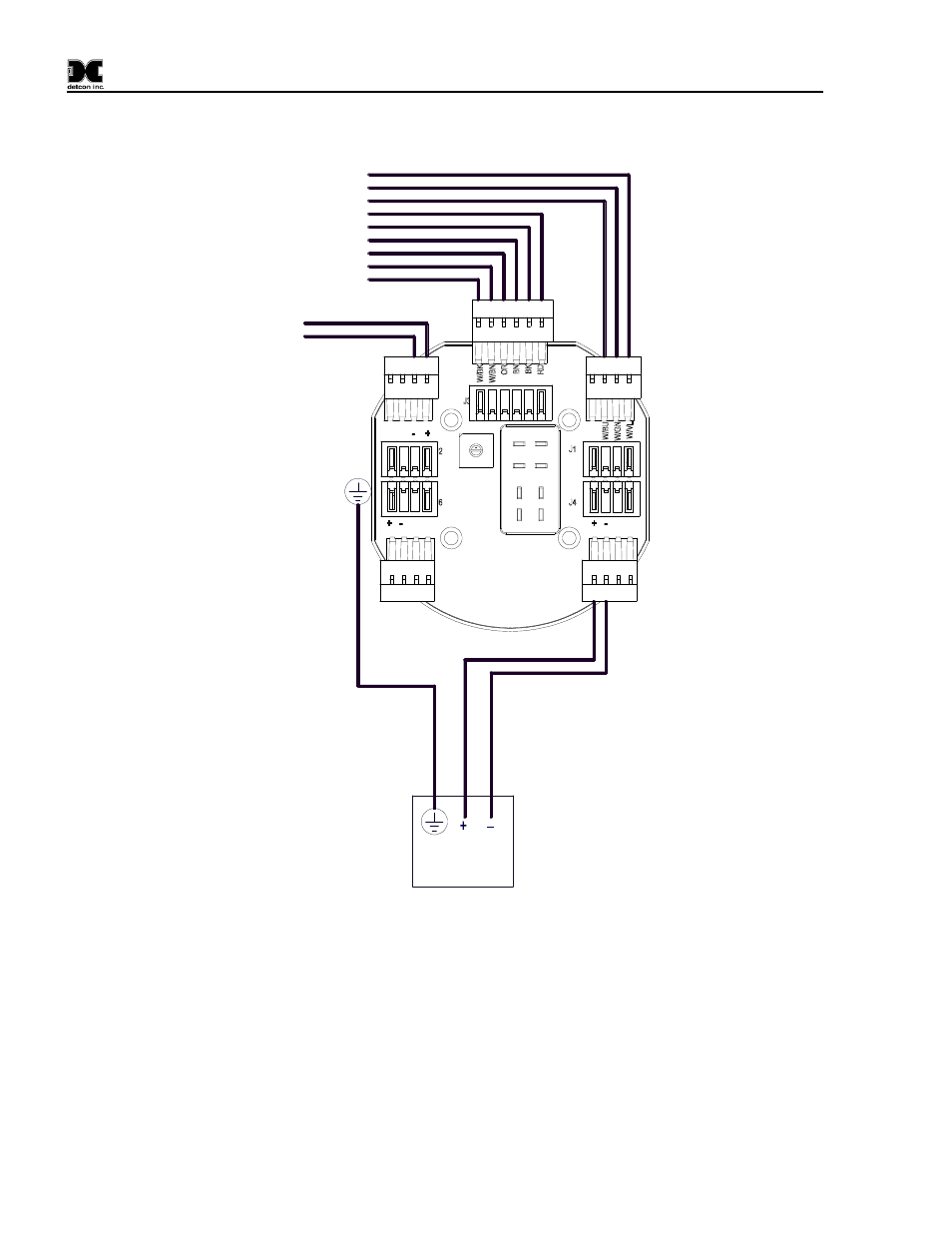
provided for connection to the 24Volt input (refer to Figure 7 Typical Unit Wiring). This voltage will be used
to charge the battery pack as well as aid in operation of the alarm station.
Gnd
Alarm Term Bd.
Strobe
White/Violet
White/Green
White/Blue
White/Brown
White/Black
Wireless
Transceiver
Brown
Black
Black
Red
G
re
en
/Y
el
lo
w
Red
Orange
External
24VDC
Input
24V Return (-)
24VDC (+)
Figure 7 Typical Unit Wiring
3.0 Operation
The Wireless C1D2 Alarm Station provides a strobe alarm. The wireless alarm station is set to respond to
alarms from the controlling unit. The controller/wireless network has independent control over the strobe, and
it will be activated when the appropriate alarm is activated.
All strobes have a flash rate of 1 Hz (one flash per second). This is preset by the manufacture and cannot be
modified.
- 12B (16 pages)
- FL-10 (7 pages)
- 10C Facilities (18 pages)
- 10C (29 pages)
- 10B (10 pages)
- 1212-N4X (9 pages)
- 812-N4X (9 pages)
- 1212B (5 pages)
- 612B (5 pages)
- 1610-N4X (28 pages)
- 1010-N4X (14 pages)
- 610-N4X (12 pages)
- 1610-N1 (4 pages)
- 810-N1-24VDC (10 pages)
- 410-N1-24VDC (4 pages)
- MCX-32-N1P (55 pages)
- RD-64X-N4X (41 pages)
- 880RA-N4X (23 pages)
- 880RA-N4X (36 pages)
- 880A-N1R (45 pages)
- 880A-N4X (43 pages)
- 880A-N4X (50 pages)
- X40-08-N4X (70 pages)
- 240 (33 pages)
- SW-AV1-N4 (12 pages)
- SW-AV2-DV1 (12 pages)
- A1V1 (9 pages)
- RXT-300 (47 pages)
- RXT-320 (31 pages)
- CXT-N4X (28 pages)
- SW-HMI-32-N4X (24 pages)
- SW-AV1-DV1 (14 pages)
- SW-AV2-DV2 (12 pages)
- SW-AV1-DV2 (12 pages)
- SmartWireless CX (33 pages)
- SmartWireless CXT (49 pages)
- CX-IR (38 pages)
- CX-DM (44 pages)
- CXT-IR (48 pages)
- CXT-DM (56 pages)
- P-1000 (28 pages)
- 1000 (32 pages)
- 1000_CO2 (32 pages)
- 1000_H2S (34 pages)