Installation, Figure 6 alarm dimensional, 0 installation – Detcon SW-AV2-DV1 User Manual
Page 9
SW-AV2-DV1
SW-AV2-DV1 Instruction Manual
Rev. 0.0
Page 5 of 8
2.0 Installation
NOTE: The wireless alarm station is a precision instrument and care should be taken when handling it.
The Wireless AV1-DV1 Alarm Station is made to be mounted on a 2” or 3” diameter pipe. Two 3” U-bolts
with hardware are provided for mounting. The location for mounting the wireless alarm station should be
carefully selected. Occasional access to the unit will be necessary for battery replacement and maintenance.
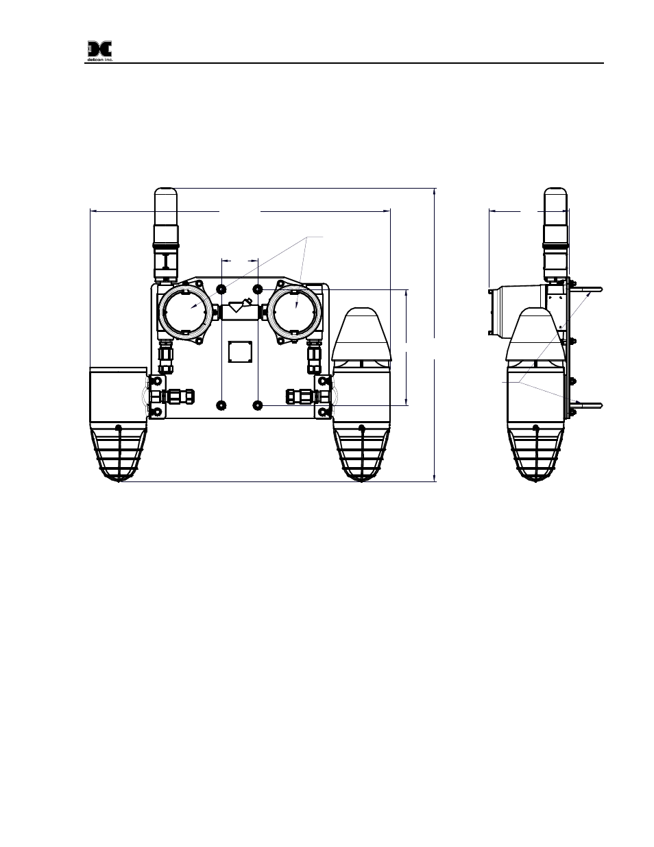
28.0"
Typ.
28.5" Typ.
11.0"
3.5"
Junction Boxes
with Battery
Packs
Strobe
Wireless Transceiver
RXT-300 or RXT-320
Strobe/Horn
Combination
7.5"
2~3" Pipe
Mounting
Hardware
Figure 6 Alarm Dimensional
No outside wiring is necessary for these units. Once the unit has been mounted, install the battery pack and
the unit will begin normal operation.
If the unit is equipped with the RXT-320 Transceiver, the Address Switch on the Wireless Interconnect PCA
should be set to the correct address for the alarm station. This switch is normally set at the factory. If there is
more than one alarm station, each station should have a unique address for proper operation. For more
information refer to the RXT-320 manual. Units equipped with RXT-300 Transceiver do not use this switch.
To install the battery pack, insure that the area is de-classified. Remove the cover from the junction box.
Release the battery catch, and install the battery. The battery can only be installed one way, and orientation is
mandated by the battery supports and the connector. Ensure that the battery is completely seated, and close the
retaining lever over the battery until it latches. The unit will power up, and begin normal operation. Replace
the cover on the junction Box, and ensure that the cover is completely screwed down and secured by the cap-
head screw.
Battery operation can be supplemented by the addition of an external 24VDC power source. The unit should
not need the addition of an external 24VDC power source, but if an external 24VDC is to be added, J6 is
provided for connection to the 24Volt input (refer to Figure 2). This voltage will be used to charge the battery
pack as well as aid in operation of the alarm station.