6 remote mounting applications, Remote mounting applications, Figure 7 typical outline and mounting dimensions – Detcon DM-534C User Manual
Page 12: Figure 8 sensor connector pcb
DM-534C Oxygen Sensor Assembly
DM-534C O2 Sensor Instruction Manual Rev.1.4
Page 8 of 18
5.5"
6.1"
5.825"
7.92"
2"
0.5"
4.65"
Wall
(o
r o
ther
mo
unt
ing surf
ace
Splash Guard
O2 Sensor
Cal Port
1/4" Mounting holes
8-32 tapped
ground point
3/4" NPT Ports
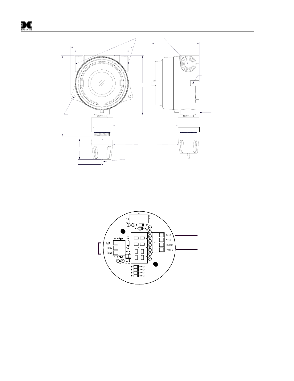
Figure 7 Typical Outline and Mounting Dimensions
c) Observing correct polarity, terminate 3-conductor field wiring to the sensor base connector board in
accordance with the detail shown in Figure 8.
d) Replace the plug-in transmitter circuit and replace the junction box cover.
Customer
Wiring
Wiring from
O2 Sensor
Blue
Blue
White
Figure 8 Sensor Connector PCB
6.6
Remote Mounting Applications
Some sensor mounting applications require that the gas sensor head be remotely mounted away from the
sensor transmitter. This is usually true in instances where the gas sensor head must be mounted in a location
that is difficult to access. Such a location creates problems for maintenance and calibration activities. Detcon
provides the DM-534C sensor in a remote-mount configuration in which the sensor (Model DM-534C-RS) and
the transmitter (Model DM-534C-RT) are provided in their own condulet housing and are interfaced together
with a three conductor cable. Reference figure Figure 9 below for wiring diagram.