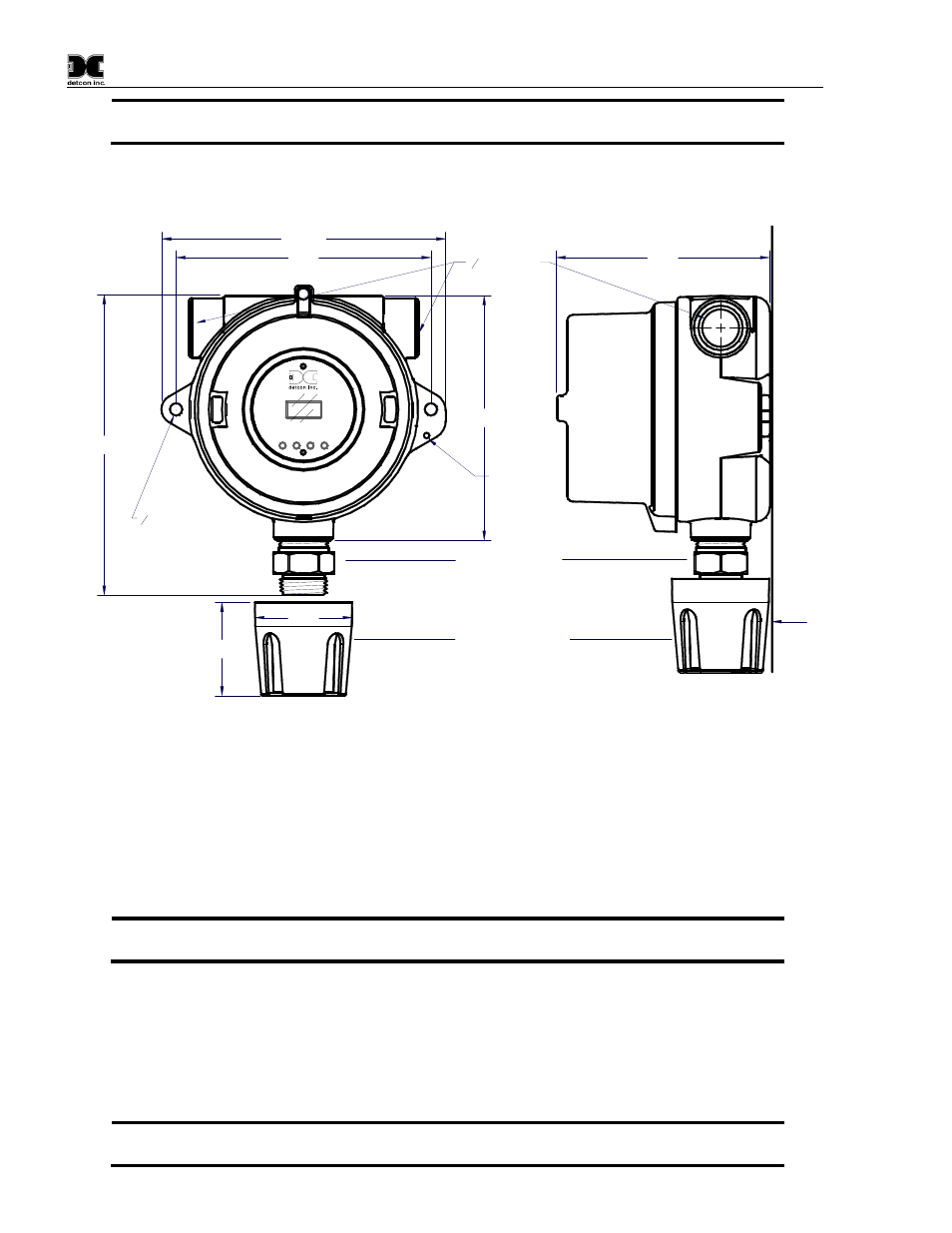
Electrical installation, Figure 7 typical outline and mounting dimensions, 5 electrical installation – Detcon TP-624D User Manual
Page 12
Model TP-624D
TP-624D Instruction Manual
Rev. 0.4
Page 8 of 40
maintained to provide a solid electrical ground path. If Teflon Tape is used the Sensor must be
externally grounded using a ground strap.
When mounting on a pole, secure the Junction Box to a suitable mounting plate and attach the mounting plate
to the pole using U-Bolts. (Pole-Mounting brackets for Detcon Junction Box’s are available separately.)
8-32 tapped
ground point
4.6"
3
4
NPT Ports
6.125"
5.5"
6.45"
1
4
" mounting holes
5.25"
W
a
ll
(o
r
o
th
e
r
m
o
u
n
ti
n
g
s
u
rf
a
c
e
)
H2S Sensor
Splash Guard
2"
2.1"
PGM
1
PGM
2
MODEL
TP-624D
HOUSTON, TEXAS
FLT
1
2
CAL
MicroSafe
H2S Gas Sensor
ALM ALM
TM
Figure 7 Typical Outline and Mounting Dimensions
2.5 Electrical Installation
The Sensor Assembly should be installed in accordance with local electrical codes. The sensor assemblies are
CSA/NRTL approved (US and Canada) for Class I, Division 1, Groups B, C, & D area classifications.
Proper electrical installation of the gas sensor is critical for conformance to Electrical Codes and to avoid
damage due to water leakage. Refer to Figure 8 and Figure 9 for proper electrical installation.
NOTE: If a conduit run exits the secondary port, repeat the installation technique shown in
Figure 8.
In Figure 8, the drain allows H
2
O condensation inside the conduit run to safely drain away from the sensor
assembly. The electrical seal fitting is required to meet the National Electrical Code per NEC Article 500-3d
(or Canadian Electrical Code Handbook Part 1 Section 18-154). Requirements for locations of electrical seals
are covered under NEC Article 501-5. Electrical seals also act as a secondary seal to prevent water from
entering the wiring terminal enclosure. However, they are not designed to provide an absolute watertight seal,
especially when used in the vertical orientation.
NOTE: A conduit seal is typically required to be located within 18" of the J-Box and Sensor
Assembly. Crouse Hinds type EYS2, EYD2 or equivalent are suitable for this purpose.