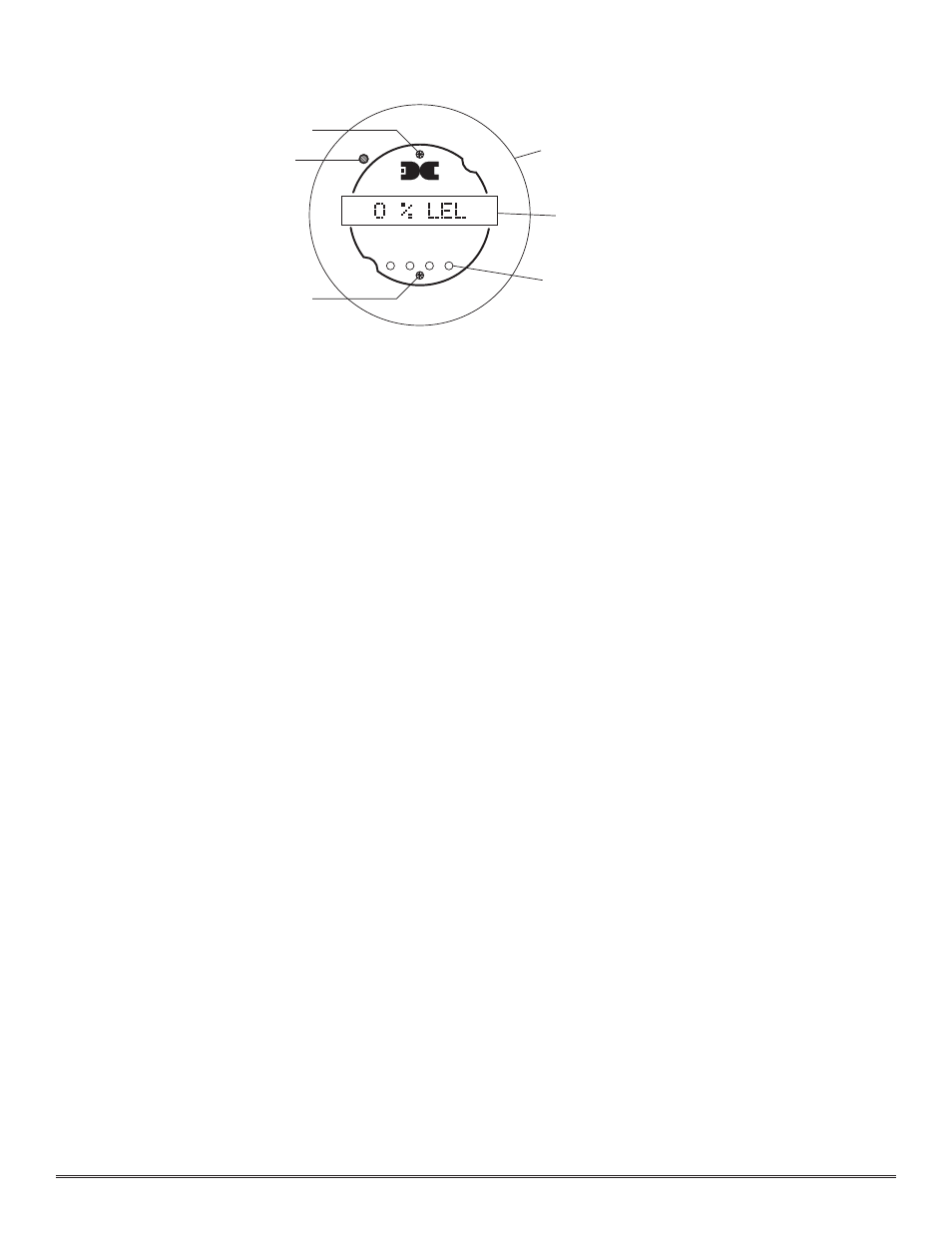
Figure #7 – Detcon IR-622 User Manual
Page 14
NOTE: If the sensor has been conf igured for calibration with a gas other than methane you will need to use
that gas. See section 3.7 for further information on calibration gas.
Material Requirements
*
Detcon PN 6132 Threaded Calibration Adapter
*
Span Gas 50% LEL methane in air at a controlled f low rate between 200 ml/min.
a)
Attach the calibration adapter to the threaded sensor housing. Apply a the test gas at a controlled f low rate of
200 ml/m. Observe that the LCD display increases to a level of 20% or higher.
b)
Remove the test gas and observe that the LCD display decreases to
“0 % LEL”.
c)
If alarms are activated during the test, and have been programmed for latching operation, reset them according to
the instructions in section 3.9.2.
Initial operational tests are complete. Detcon combustible gas sensors are pre-calibrated prior to shipment and will,
in most cases, not require signif icant adjustment on start up. However, it is recommended that a complete calibra-
tion test and adjustment be performed within 24 hours of installation. Refer to calibration instructions in later text.
3.7 C
ALIBRATION
Material Requirements
*
Detcon PN 3270 MicroSafe™ Programming Magnet
*
Detcon PN 6132 Threaded Calibration Adapter
*
Span Gas containing the applicable calibration gas in air. Span gas concentration is recommended at 50% of
range (which is the factory default) at a controlled f low rate of 200 ml/min. Other concentrations can be used
as long as they fall within 10% to 90% of range. See section 3.7.2 for details.
3.7.1 Calibration Procedure - Zero
NOTE: Before performing a zero calibration, be sure there is no background target gas present.
a)
Enter the calibration menu by holding the programming magnet stationary over “PGM 1” (see figure 7) for 3 sec-
onds until the display reads
“1-ZERO 2-SPAN”, then withdraw the magnet. Note that the “CAL” LED is on.
b)
Next, enter the zero menu by holding the magnet stationary over “PGM 1” for 3 seconds until the display
reads:
“ZERO 0%”, then withdraw the magnet. The sensor has now entered the auto zero mode. When it is
complete the display will read
“ZERO COMPLETE” for 5 seconds and then return to the normal operations
menu,
“0 % LEL”.
NOTE 1: If the circuitry is unable to adjust the zero to the proper setting the sensor will enter a calibration
fault mode which will cause the display to alternate between the sensor’s current status reading and the calibra-
tion fault screen which appears as:
“CAL FAULT” (see section 3.7.3).
Detcon Model IR-622 Combustible Hydrocarbon Sensor PG.14
detcon inc.
Program Switch #2
FLT
ALM
1
CAL
MicroSafe™ LEL Gas Sensor
HOUSTON, TEXAS
PGM
2
PGM
1
ALM
2
MODEL
IR-622
CONTRAST
Alarm & Cal LEDs
Program Switch #1
Menu Driven Display
Plug-in Microprocessor Control Circuit
Display Contrast Adjust
Figure #7