Figure #3, Figure #2 – Detcon IR-622 User Manual
Page 10
a)
Remove the junction box cover and un-plug the control circuit by grasping the two thumb screws and pulling outward.
b)
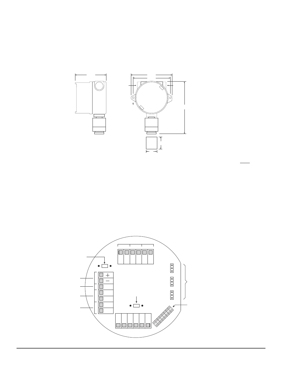
Securely mount the sensor junction box in accordance with recommended practice. See dimensional drawing (Fig. 2).
c)
Observing correct polarity, terminate 3 conductor field wiring, RS-485 wiring, and applicable alarm wiring to the
sensor base connector board in accordance with the detail shown in Figure 3. Normally open and normally closed
Form C dry contacts (rated 5 amp @ 120VAC; 5 amp @ 30VDC) are provided for Fault, Alarm 1, and Alarm 2.
Note: Per U.L. approval, these relays may only be used in connecting to devices that are powerd by the same
voltages.
d)
Position gold plated jumper tabs located on the connector board in accordance with desired Form C dry con-
tact outputs: NO = Normally Open; NC = Normally closed (see f igure 3).
Note: If a voltage signal output is desired in place of the 4-20mA output, a 1/4 watt resistor must be installed
in position R2 of the terminal board. A 250
Ω resistor will provide a 1-5V output (– to mA). A 100Ω resistor will
provide a .4-2V output, etc. This linear signal corresponds to 0-100% of scale (see f igure 3).
e)
Program the alarms via the gold plated jumper tab positions located on the CPU board (see f igure 4). Alarm 1
and Alarm 2 have three jumper programmable functions: latching/non-latching relays, normally energized/nor-
mally de-energized relays, and ascending/descending alarm set points. The fault alarm has two jumper program-
mable functions: latching/non-latching relay, and normally energized/normally de-energized relay. The default
Detcon Model IR-622 Combustible Hydrocarbon Sensor PG.10
NC
ALARM 1
W
H
T
B
L
K
Y
E
L
B
LU
MA
VDC Power In
Optional RS-485
Terminating Resistor
Use 120 ohm
NO
NC
NO
NC
NO
N
O
/N
C
C
O
M
N
O
/N
C
C
O
M
N
O
/N
C
C
O
M
FAULT
ALM-2
ALM-1
Alarm Dry Contacts
ALARM 2
FAULT
R1
R2
A
B
A
B
4-20 mA Output
RS-485 In
RS-485 Out
Optional 4-20 mA
Signal Developing Resistor
Use 250 ohm 1/4w
JU
M
P
E
R
S
U
N
-U
S
E
D
R
E
D
B
R
N
Jumper Programmable Alarm Outputs
Normally Open or Normally Closed
Sensor
Place un-used alarm programming
jumper tabs here
Figure #3
4 3/4"
3/4" NPT
1/4" Dia.
Mounting Holes
8 1/4"
6 1/8"
5 1/2"
3/4" NPT
Rainshield/
Splashguard
2"
2 1/8"
Figure #2