Installation, Dimensions, Electrical connections – AW Gear Meters DSV-100 User Manual
Page 4
AW-Lake Company 8809 Industrial Drive, Franksville, WI 53126 web: www.awgearmeters.com
Tel: 262-884-9800 Fax: 262-884-9810 Email: [email protected]
REV. 1.6 03/10 DSV-100 Manual.DOC
3
Installation
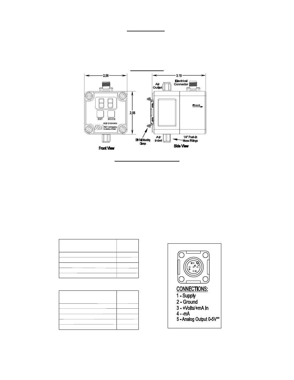
The DSV-100 has DIN rail mounting provisions on the back of the unit. Units can be mounted directly
beside each other for maximum panel component density. It is recommended to install the unit oriented
horizontally as shown below or vertically on it’s back. Air fittings are push-in type ¼” O.D. pneumatic
hose connectors.
Dimensions
Electrical Connections
Power and signal connections to the DSV-100 are through a 5-pin threaded circular connector (4-pin
connector on versions preceding 1.6). The use of shielded cable is recommended and the shield should be
connected to earth ground at the source.
The DSV-100 requires a 10-24 VDC @ 35-136 mA supply for
operation. See specifications for complete voltage and current requirements. The DSV-100 will respond
to either voltage or current control determined by electrical connection and input option selection. See
Input/Output Options and Input/Output Options Programming on page 4 for input options. Voltage or
current control is referenced to Supply Common or the DSV-100 will accept a fully isolated mA input
when isolated mA input mode is selected in set-up. (On versions prior to 1.6 the –mA input must be
connected to supply common for proper operation when a current control input is used).
Connection for Voltage Input
Connection for Current Input
* -mA Control Signal must be connected to the Supply Common for proper operation on DSV-100 versions
previous to 1.6. For version 1.6 and up isolated mA input operation is permitted when selected in set-up.
** Analog output available on version 1.6 and up only.
10-24 VDC Supply
Electrical
Connection
Supply/Signal Common
+ Volts Control Signal
No Connection
Analog Pressure Output**
Connector
Pin
1
2
3
4
5**
10-24 VDC Supply
Electrical
Connection
Supply Common*
+ mA Control Signal
- mA Control Signal*
Analog Pressure Output**
Connector
Pin
1
2*
3
4*
5**