Display/programming buttons and magnetic switches, Programming, D isplay/program m in g button loc ation s – AW Gear Meters RT-Ex15-Ex User Manual
Page 7: M agn etic sw itc h loc ation s
AW-Lake Company 8809 Industrial Drive, Franksville, WI 53126 web: www.awgearmeters.com
Tel: 262-884-9800 Fax: 262-884-9810 Email: [email protected]
RT-Ex15-Ex manual rev 6.13.11.docx
Revision 3.3.10
7
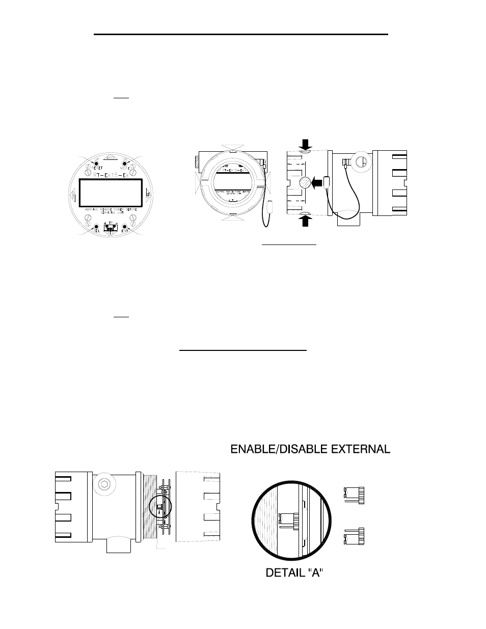
Display/Programming Buttons and Magnetic Switches
Display mode changes, reset of total and programming functions are accomplished using the
buttons located on the face plate when the cover is off or external to the cover using the magnetic
switches. The magnetic switches are located at the 3, 6, 9 and 12 o’clock positions on the side of
the housing. The function of each position is indicated on the faceplate of the RT-Ex15-Ex.
Touching the side of the magnet wand to the appropriate location will activate the magnetic
switches.
Disable External Programming
All programming is initiated by using the ENT button located on the face plate when the cover is
off or external to the cover using the ENT magnetic switch when the cover is installed. The ENT
external magnetic switch can be disabled to prevent programming when the cover is on. A
jumper is located on the back of the main circuit board on the edge at the 9 o’clock position. If
the jumper is set to disable the ENT magnetic switch, the MODE and RESET external magnetic
switches are still active to allow mode changes and total reset but program changes can not be
made without removing the cover and using the ENT button on the faceplate. The default is
switch enabled.
M AGN ETIC
SW ITC H
(EN T)
GT
GAL
GPD
RA 002.50
TA 003.23
M AGN ETIC
SW ITC H
(SEL)
M AGN ETIC
SW ITC H (M OD E/D N )
M AGN ETIC
SW ITC H (RESET/UP)
M OD E/D N
BUTTON
RESET/UP
BUTTON
SEL
BUTTON
EN T
BUTTON
D ISPLAY/PROGRAM M IN G
BUTTON LOC ATION S
RA 002.50
TA 003.23
GPD
GAL
GT
D N /
M O D E
R ES ET
EN T
U P /
S EL
M AGN ETIC SW ITC H LOC ATION S
TOUCH SID E OF M AGN ET TO SW ITC H LOC ATION
1 1
4
1 1
4
ENABLE/DISABLE EXTERNAL
PROGRAMMING JUMPER ON BACK
OF MAIN CIRCUIT BOARD AT THE
EDGE IN 9 O'CLOCK POSITION
(SEE DETAIL "A")
"ENT" MAGNETIC
SWITCH DISABLED
JUMP 2 & 3
1
2
3
3
2
1
"ENT" MAGNETIC
SWITCH ENABLED
JUMP 1 & 2
PROGRAMMING