Aposonic A-S0401R1 User Manual
Page 9
9
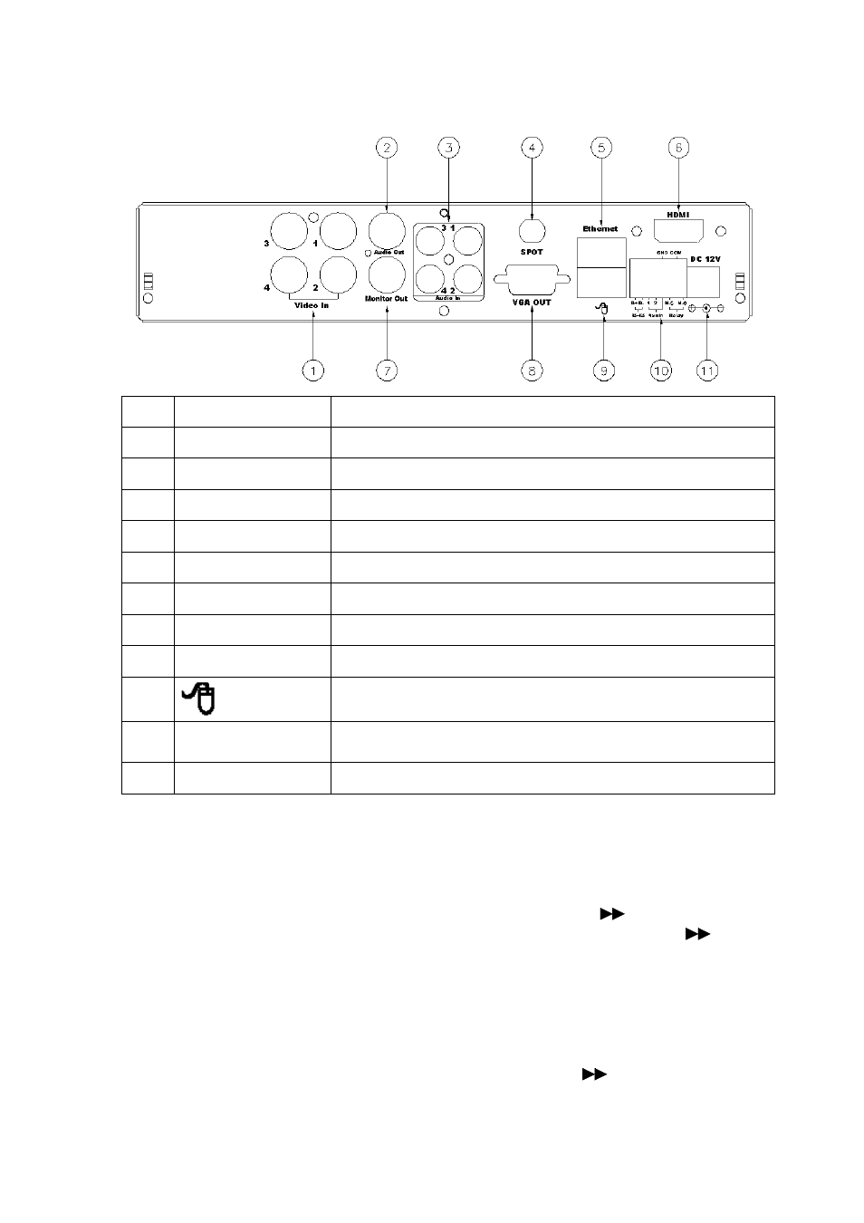
2.2 BACK
PANEL
NO. LABEL
OPERATION
1 VIDEO
INPUT Video input with BNC connector.
2 AUDIO
OUT
Audio output
3 AUDIO
IN
Audio input.
4 SPOT
SPOT connector (Reserved)
5 ETHERNET
RJ-45 connector for network.
6 HDMI
HDMI connector (Reserved)
7 MONITOR
OUT Video output with BNC connector.
8
VGA D-SUB OUT Connect to CRT or LCD monitor.
9
USB Mouse Connector
10
RS-485/ ALARM/
RELAY
2 pin connector for external control unit, 2 pin connector for
Alarm input and 3 pin connector for relay
11 POWER
Power switcher: DC 12V 3.0A / 50-60 Hz input.
NOTE: DO NOT REMOVE and PLUG IN the supplied mouse while DVR is
operating.
2.3 ADVANCED AUTO SWITCH, ZOOM, PTZ, COPY KEY CONTROL & USB
INFORMATION
AUTO SWITCH : In the split screen mode, use the “QUAD+
” keys in the front
panel to enable auto switch function. Moreover, press “
” key
again to disable it.
ZOOM :In the full screen mode, user can use compound key “ ENTER/ COPY ” on the
front panel to perform ZOOM function. Press ▲▼◄►, located on the front
panel, to move the zoom window.
PTZ : When camera supported PTZ function, user can use “
” button on the front
panel to perform PTZ function. Press ▲▼◄► to select and change setup value.