Filter housing dimensions & weights, Installation, Important – Van Air Systems AHP High Pressure Alloy Filter Series IOM User Manual
Page 2
PAGE 2
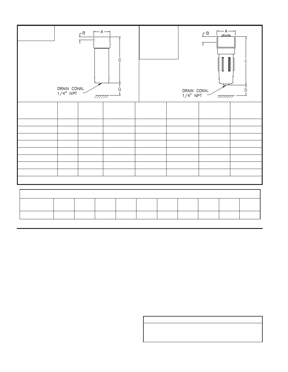
FILTER HOUSING DIMENSIONS & WEIGHTS
DIMENSIONS FOR:
AHP-65
AHP-80
AHP-125
AHP-255
AHP-285
AHP-470
DIMENSIONS FOR:
AHP-25
AHP-40
*Insert appropriate filtration grade here; for example AHP-25-7.25-B.
**Flow is based on SCFM @ 725 PSIG @ 100°F.
FILTER MODEL
FLOW**
(SCFM)
IN/OUT
CONN.
(NPT)
A
B
C
D
HOUSING
WEIGHT
(LBS)
AHP-25-7.25-(*)
94
1/4"
2-1/2"
1/2"
6"
2"
0.5
AHP-40-7.25-(*)
147
3/8"
2-1/2"
1/2"
7-1/2"
2"
0.6
AHP-65-7.25-(*)
265
1/2"
4-1/2"
1-1/2"
12"
6"
5.7
AHP-80-7.25-(*)
324
3/4"
4-1/2"
1-1/2"
12"
6"
5.7
AHP-125-7.25-(*)
492
1"
4-1/2"
1-1/2"
15-1/2"
6"
7.3
AHP-255-7.25-(*)
1015
1-1/2"
5-3/4"
2"
21"
7"
16.5
AHP-285-7.25-(*)
1132
2"
5-3/4"
2"
21"
7"
16.5
AHP-470-7.25-(*)
1882
2"
5-3/4"
2"
25"
7"
22
FLOW CORRECTION FACTORS FOR OTHER PRESSURES
OPERATING
PRESSURE
100
PSIG
250
PSIG
300
PSIG
400
PSIG
500
PSIG
550
PSIG
600
PSIG
650
PSIG
700
PSIG
725
PSIG
Correction Factor
0.25
0.51
0.57
0.66
0.77
0.82
0.87
0.92
0.98
1.00
1. Before installing filter, check operating temperature and
pressure conditions to verify that they are within the specified
ranges.
(See Operating Conditions on page 1). Also verify
that system flow rate corresponds to the rated capacity of
the filter. Operating at flows above rated capacity will result
in increased pressure drop.
2. Locate Filter at the point of lowest operating temperature to
ensure that water and oil vapor do not condense downstream
of the filter. Filter should be installed close to the point of
use to minimize the risk of pipe scale, dirt, etc. recontaminat-
ing the compressed air. This is particularly important when
installing a new filter on an existing system that has not had
proper filtration.
3. Protect filter from reverse flow conditions. Do not install filter
downstream of quick opening valves.
4. Install filter vertically. Provide required minimum clearance
below filter to allow for replacement of element.
(See Element Removal Clearance on page 2).
5. Remove filter head from the bowl by turning bowl counter-
clockwise. Pull element from filter head. Set bowl and
element aside for use later.
INSTALLATION
6. Install inlet and outlet shutoff valves to facilitate replace-
ment of element. Bypass piping is recommended.
(See Fig-
ure 1A). MAKE SURE VALVES ARE CLOSED BEFORE
PROCEEDING.
7. Depressurize piping and connect filter head into piping. Avoid
reducers or bushings to match inlet size. The resulting restric-
tion will increase pressure drop. Make sure head is installed
with flow arrows pointing in proper direction. Use pipe thread
compound as required.
If multiple filters are being installed in series, use pipe nipples
to connect filters,
do not attempt to bolt filters together.
8. Install element by pushing into filter head.
IMPORTANT
INSTALL FILTER HEAD WITH ARROWS POINTING
IN THE PROPER DIRECTION TO ENSURE PROPER
OPERATION. (SEE FIGURE 1A).