0 installation, 0 operation, 1 location – Van Air Systems PLD 8-2.8 / 36-2.8 User Manual
Page 2: Maximum capacities - mscfd
MODEL
NO.
PLD 8-2.8
PLD 12-2.8
PLD 16-2.8
PLD 20-2.8
PLD 24-2.8
PLD 30-2.8
PLD 36-2.8
PAGE 2
2.0 INSTALLATION
2.1 LOCATION
The ability of a dehydrator to dry natural gas is dependent on
the correct location of the unit. Temperature and pressure are
the keys to selecting the proper location.
INLET GAS TEMPERATURE: Lower inlet gas temperatures will
result in a lower moisture content at the outlet of the dehydrator.
Locate the dehydrator at the point where temperature is the lowest.
CAPACITY: The chart below indicates the maximum flow rate
through the dehydrator for a 24 HOUR period. To calculate the
capacity for a rate per minute just multiply the
MSCFD RATE (from
chart ) by 0.6944 example:
A PLD 12-2.8 operating at 50 PSIG has a maximum MSCFD rate of
79. To figure the SCFM multiply 79 MSCFD x 0.6944 which equals
54.86SCFM
NOTE: This is the MAX instantanious flow that can be processed
through the dehydrator without deterioration of the drying
performance.
OPERATING PRESSURE: More gas can be processed through the
dehydrator at higher pressures. Locate the dehydrator at the highest
practical pressure, but do not exceed the maximum rated working
pressure of the dehydrator. Refer to the capacity chart located below.
AFTERCOOLING: If the gas being processed has been compressed
mechanically, an aftercooler, finned tubing or extended run of piping
will usually be necessary to reduce the inlet gas temperature to the
dehydrator.
MAXIMUM CAPACITIES - MSCFD
1,000 STANDARD CUBIC FEET PER DAY
250 PSIG
173
325
510
786
1147
1831
2749
225 PSIG
157
294
462
712
1038
1658
2490
200 PSIG
141
263
413
638
930
1485
2230
175 PSIG
124
233
365
563
822
1312
1970
150 PSIG
108
202
317
489
714
1139
1711
100 PSIG
75
141
221
341
497
793
1191
50 PSIG
42
79
125
192
280
447
672
MAXIMUM
WORKING
PRESSURE
280 PSIG
280 PSIG
280 PSIG
280 PSIG
280 PSIG
280 PSIG
280 PSIG
PART
NO.
80-1397
80-1399
80-1401
80-1403
80-1405
80-1468
80-1407
ALWAYS PROCESS THE GAS THROUGH THE
DEHYDRATOR AT THE LOWEST TEMPERATURE
AND THE HIGHEST PRESSURE.
IMPORTANT
280 PSIG
193
362
567
875
1277
2038
3061
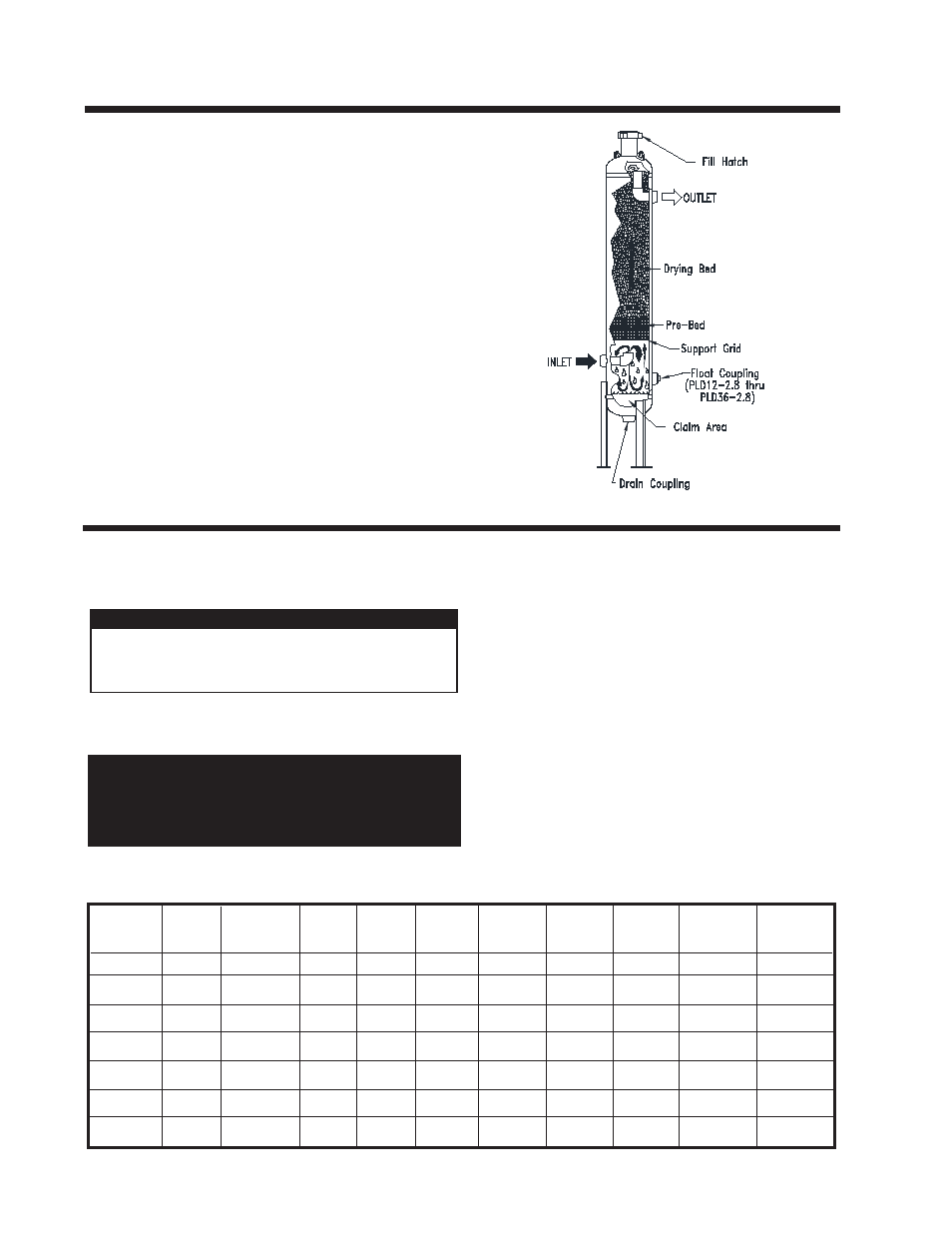
1.0 OPERATION
A Pipeline Dehydrator removes the water vapor (humidity) pres-
ent in the gas stream. The process cleans and dries the gas as it
flows through a vessel which is filled with a special drying agent
(desiccant). The dehydrator operates automatically. There are no
moving parts and no external source of power is required.
"Wet" natural gas enters the lower portion of the dryer where liquid
water and solid particles are separated by gravity and fall to the
bottom of the vessel. The gas moves upward through the prebed
and drying bed of Van Gas desiccant tablets. The tablets attract
and absorb moisture from the gas as it flows through the desiccant
bed. The tablets dissolve gradually as they absorb the moisture
and the liquid falls to the bottom of the vessel. The liquid run off in
the prebed creates an extended surface area capable of removing
additional moisture from the gas. This conserves the absorbent
desiccant tablets. The "dry" natural gas flows through the dryer
outlet.
The solution of dissolved desiccant and water that falls into the
claim area at the bottom of the vessel must be drained regularly to
prevent the vessel from flooding. An automatic drain valve can be
installed to prevent the vessel from flooding.
CAUTION
The gas temperature should not exceed:
100°F for GASDRY PRIME
80°F for GASDRY PEAK
100°F for GASDRY MAX