Van Air Systems HLS-50-HLS-150 User Manual
Page 7
PRINTED IN THE U.S.A.
PAGE 7
USING THE DRYER
SECTION 7
7.1 CONTROLLER
The Controller is a compact NEMA 4 control box. It has the following features:
• Dryer Status LEDs
- POWER ON LED - L/R TOWER DRYING LEDS
- RUN LED - L/R TOWER REGENERATING
LEDS
- HOLD LED - DRYER PURGING LED
- SWITCHING FAILURE LED
The Dryer Status LEDs are located on the front panel of the control box.
Figure 7A shows the location of each.
When the Left tower is pressurized and on line drying the process air, the
corresponding LEFT TOWER DRYING LED is illuminated. When the right
tower is pressurized and on line drying the process air, the corresponding
RIGHT TOWER DRYING LED is illuminated.
The DRYER PURGING LED is illuminated when the purge exhaust valve
is energized open. During repressurization this LED will not be illuminated.
Repressurization occurs for approximately 20 seconds just before tower
changeover.
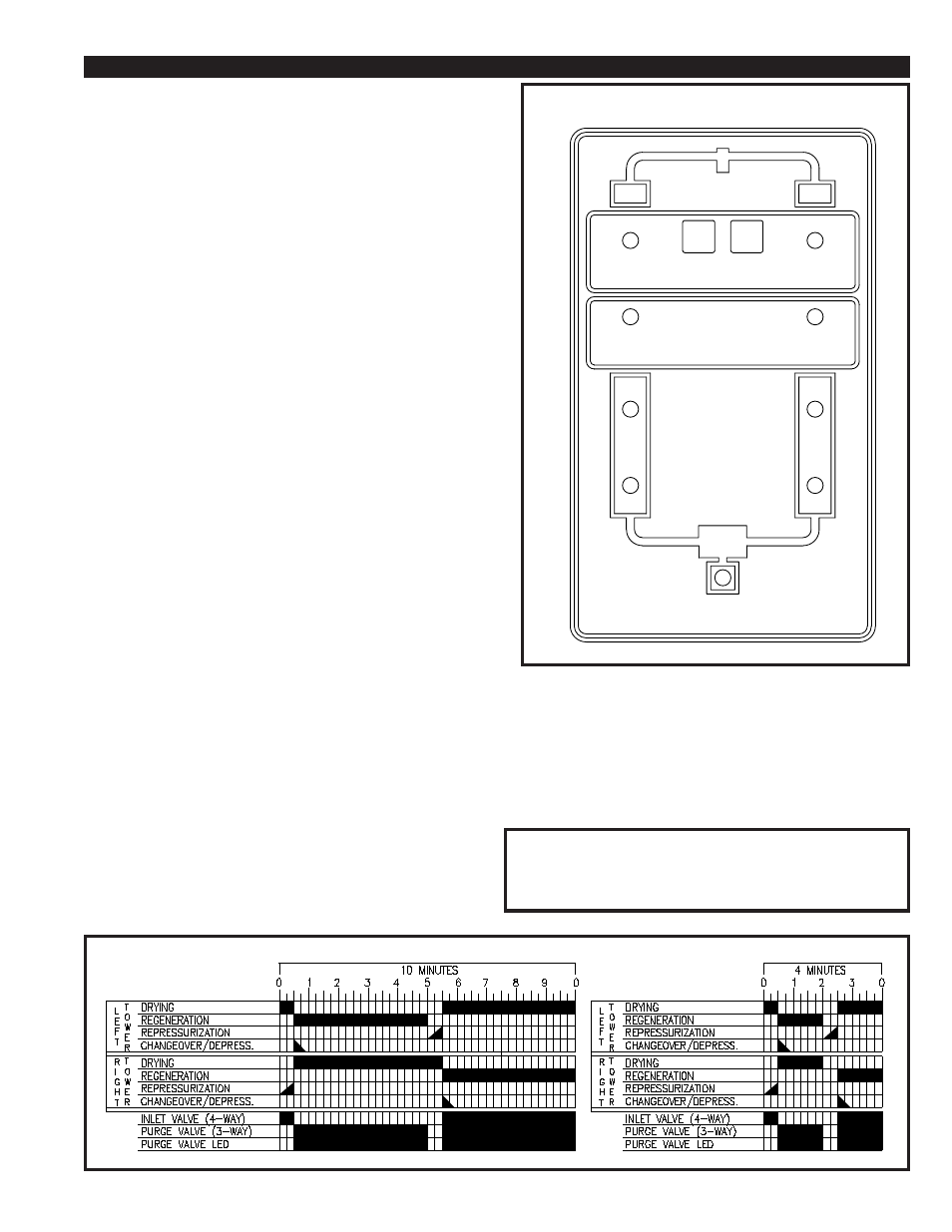
The operation sequence of the dryer is shown in FIGURE 7B TIMING
CHART.
FIGURE 7A
LEFT
RIGHT
POWER ON
STOP
RUN
RUN
TOWER DRYING
HOLD
SWITCHING FAILURE
TOWER REGENERATING
DRYER PURGING
SWITCHING FAILURE:
When there is a switching failure, the LED will be lit. This will energize
the contacts shown in FIGURE 4B. The contacts can be wired for
remote annunciation. To reset the Switching Failure Alarm press the
run button on the control box front panel.
HOLD FEATURE:
For low load or static pressure conditions, the hold contacts shown on
Figure 4B can be wired to an auxillary set of normally closed contacts
on the compressor starter. This will stop the cycling of the dryer and
repressurize both towers of the dryer, until there is demand on the
compressor. The Hold LED will light, if the dryer is wired as described
and the compressor is not running.
IMPORTANT
Operating this dryer on the 4 minute cycle will more than
double the wear on the dryer components. To reduce wear on
the dryer, operate the dryer on the 10 minute cycle if the -40
O
F
dew point is acceptable.
7.2 SETTING THE CYCLE TIME
Reference Figure 4B:
The setting for the time cycle is a 5 min/half cycle. For the half cycle
time setting, the switches indicated for DS1 (2, 5, 7, & 8) as shown in
the CYCLE TIME DETAIL have been factory set by pushing the
switches up. The values for these switches are (256, 32, 8, & 4) sec.,
so when added together equal 300 sec or 5 min. WE DO NOT
RECOMMEND
a time cycle setting below 2 min/half cycle. For this
half cycle time setting, the switches that need to be pushed up are DS1
(4, 5, 6, & 7)
there values are (64, 32, 16, & 8) sec. so when added
together equal 120 sec or 2 min.
The setting for the pressurization time is 20 sec. For the pressuriza-
tion time setting, the switches indicated for DS2 (2 & 4) as shown in
the CYCLE TIME DETAIL have been factory set by pushing the
switches up. The values for these switches are (16 & 4) sec., so when
added together equal 20sec. WE DO NOT RECOMMEND CHANG-
ING THIS SETTING.
The setting for the alarm time is 96 sec. For the alarm time setting,
the switches indicated for DS2 (5 & 6) as shown in the CYCLE TIME
DETAIL
have been factory set by pushing the switches up. The values
for these switches are (64 & 32) sec., so when added together equal
96 sec. WE DO NOT RECOMMEND CHANGING THIS SETTING.
NOTE: THE ALARM TIME SETTING NEEDS TO BE LESS THEN
THE HALF CYCLE TIME SETTING OR THIS WILL NEGATE
THE ALARM FUNCTION.
FIGURE 7B CYCLE TIMING CHART