Van Air Systems HLS-50-HLS-150 User Manual
Page 5
PRINTED IN THE U.S.A.
PAGE 5
INSTALLING THE DRYER
SECTION 4
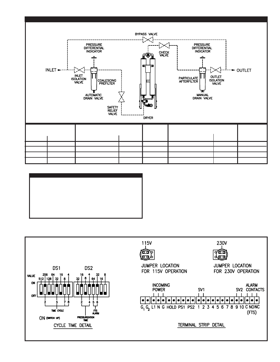
FIGURE 4A RECOMMENDED PIPING CONFIGURATION AND COMPONENTS
MODEL
HLS-55
HLS-80
HLS-120
HLS-150
DRYER
IN/OUT
1/2" NPT(F)
1"
NPT(F)
1"
NPT(F)
1" NPT(F)
MODEL
F200-0055-1/2-C-AD
F200-0085-3/4-C-AD
F200-0150-1-C-AD
F200-0150-1-C-AD
IN/OUT
1/2"
NPT(F)
3/4"
NPT(F)
1"
NPT(F)
1" NPT(F)
DEL-P
INDICATOR
MODEL
PD-6
PD-6
PD-6
PD-6
MODEL
F200-0055-1/2-RB-MD
F200-0085-3/4-RB-MD
F200-0150-1-RB-MD
F200-0150-1-RB-MD
IN/OUT
1/2"
NPT(F)
3/4"
NPT(F)
1"
NPT(F)
1" NPT(F)
PREFILTER
AFTERFILTER
DEL-P
INDICATOR
MODEL
PD-6
PD-6
PD-6
PD-6
FIGURE 4B ELECTRICAL CONNECTIONS
4.6 ELECTRICAL CONNECTIONS
WARNING
SERIOUS PERSONAL INJURY AND DAMAGE TO THE DRYER
WILL OCCUR IF THE DRYER IS CONNECTED TO A POWER
SOURCE OTHER THAN THE VOLTAGE LISTED ON THE DATA
TAG.
WHEN INSTALLING THE ELECTRICAL CONNECTIONS FOR
THIS DRYER, COMPLY WITH NATIONAL ELECTRICAL CODE
AND ALL APPLICABLE FEDERAL, STATE AND LOCAL
CODES.
The power supply to the dryer will be connected into the dryer control
box. A 7/8" dia hole was provided in the bottom of the box for the
connection of conduit or a cord grip connector.
Check the electrical rating of the dryer as listed on the dryer data tag.
Make sure that the power source is correct for the dryer rating.
Remove the box cover to access the power supply and alarm
terminals. Wire the power supply as shown in Figure 4B. Connect
the wiring and necessary components to the dryer box. Comply with
all codes applicable for this installation.