Section 4 - installation, 4 pressure relief valves, 1 location – Van Air Systems HLSXG-55 User Manual
Page 5: 2 piping and ancillary equipment, 5 purge exhaust piping, 3 filters
PAGE 5
INSTALLING THE DRYER
SECTION 4
4.4 PRESSURE RELIEF VALVES
CAUTION
THESE ASME CODE VESSELS MUST BE PROTECTED BY
PRESSURE RELIEF VALVES. Refer to OSHA 1910.169 Par. b, Sub.
Par (3) and ASME Boiler and Pressure Vessel Code, Section VIII,
Division 1, UG-125 through UG-136. Also comply with all state
and local codes.
Two connections were provided in the outlet piping of the dryer for the
installation of customer supplied pressure relief valves. Reference
SECTION 3.2 for location.
4.1 LOCATION
WARNING
DO NOT INSTALL THIS DRYER IN AN ENVIRONMENT OF
CORROSIVE CHEMICALS, POISONOUS GASSES, OR
SATURATED STEAM HEAT.
Locate dryer in a protected, well vented area where ambient
temperatures are between 40
o
F and 120
o
F. Allow sufficient clearance
over and around the dryer for access to desiccant fill and drain ports
and controls.
Refer to SECTION 3.2 for dryer dimensions.
Position the dryer in the upright position on a solid, level, vibration free
surface capable of supporting the dryer’s weight.
Refer to SECTION
3.1 for dryer specifications.
The dryer should not be located in extremely dirty areas where
airborne contaminants can accumulate on the dryer. If this cannot be
prevented, the dryer should be cleaned periodically.
Once the location has been determined, place the dryer into position.
Reference SECTION 1 for handling instructions.
4.2 PIPING AND ANCILLARY EQUIPMENT
CAUTION
Make sure that the inlet gas piping is connected to the LOWER
connection of the dryer system and the outlet gas piping is connected
to the UPPER connection of the dryer system. Reference SECTION 3.2.
Make sure that the inlet and outlet piping are properly supported.
Excessive stress may cause damage and/or dryer malfunction.
Remove protective caps or covers from all piping connections before
installing this dryer.
If this dryer is to be installed into an existing piping system, clean the
existing inlet piping to remove all accumulated dirt, pipe scale, etc.,
before connecting the dryer. See
FIGURE 4A for Recommended
Piping Conficuration. Make sure the inlet and outlet shutoff valves are
tightly closed before connecting to the existing piping system.
If excessive vibrations are present in the piping, install a flexible hose
between the compressor and the dryer inlet.
When installing the piping and any additional components, make sure
that adequate pipe supports are used. Excessive stress on the dryer
and components may cause damage or premature failure. Use either
overhead or stiff-leg type supports.
Make sure that the piping is correctly connected to the dryer.
Reference SECTION 3.2 for dryer dimensions and connection
locations.
4.5 PURGE EXHAUST PIPING
A 1/2" NPT female purge connection is provided on the dryer. Solenoid
valve and control line relief valve exhausts also run into this exhaust
port.
See SECTION 3.2 for location. The customer is responsible to
pipe the purge to flair or to re-entrain it to the compressor intake.
IMPORTANT
Make sure that the piping is as short as possible and does not
create back pressure on the dryer. To prevent liquid
accumulation in the piping and purge valve, the piping must be
at the same level or lower than the purge valve.
If the ambient temperature is subject to temperatures below 40
o
F,
freeze protection must be installed.
The distance will determine the size of piping that is recommended.
For distances of 10 feet or less, use piping of the same size as the
purge valves. For distances up to 20 feet, use piping one size larger
than the purge valves.
A high efficiency coalescing prefilter should be installed before the
dryer to remove lubricating oils, dust and pipe scale contamination. A
general purpose particulate afterfilter should be installed downstream
of the dryer to remove and desiccant dust. It is recommended that the
pre and after filters have pressure differential gauges to monitor ele-
ment life.
See FIGURE 4C for recommended pre and after filters.
4.3 FILTERS
CAUTION
THE DRYER IS NOT DESIGNED TO HANDLE LIQUID WATER. IF
LIQUID WATER IS PRESENT IN THE GAS SYSTEM, A
SEPARATOR WITH AN AUTOMATIC DRAIN MUST BE IN-
STALLED UPSTREAM OF THE DRYER SYSTEM TO PREVENT
FLOODING.
Make sure that the elements are installed in all filter housings
prior to start up.
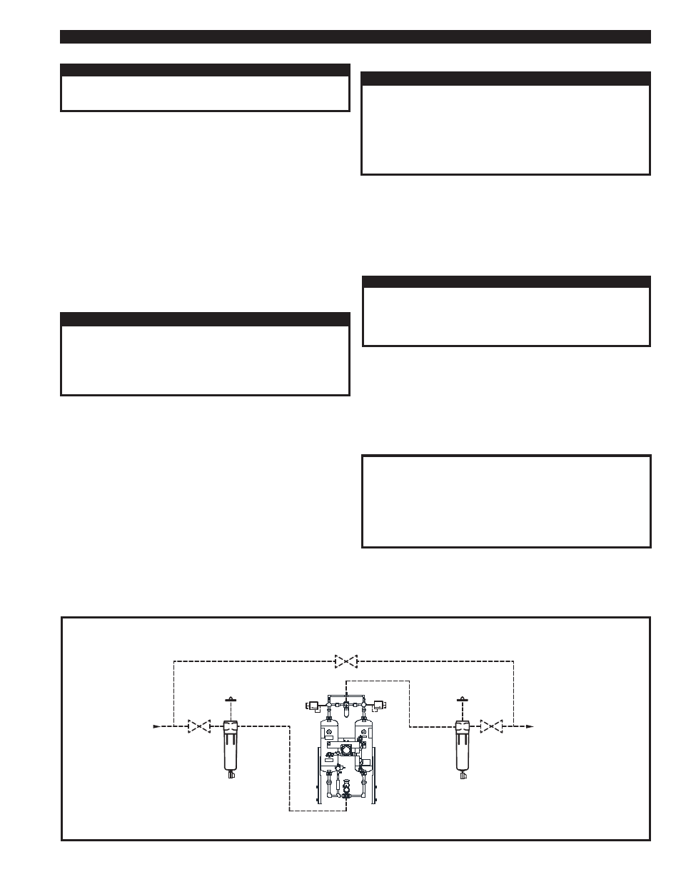
FIGURE 4A RECOMMENDED PIPING CONFIGURATION AND COMPONENTS
NOTE:
Components shown here are
NOT supplied with the dryer.
MANUAL
DRAIN VALVE
DRYER
MANUAL
DRAIN VALVE
INLET
ISOLATION
VALVE
OUTLET
ISOLATION
VALVE
BYPASS VALVE
PRESSURE
DIFFERENTIAL
INDICATOR
PRESSURE
DIFFERENTIAL
INDICATOR
INLET
OUTLET
COALESCING
PREFILTER
PARTICULATE
PREFILTER
SAFETY
RELIEF
VALVE
TYP