Page 3, Caution – Van Air Systems MHL3-MHL50 User Manual
Page 3
Van Air Systems MHL-Series Desiccant Air Dryer Operations and Maintenance Manual
Page 3
SECTION 2 SAFETY INSTRUCTIONS
2.1
INSTALLATION/MAINTENANCE SAFETY
Before starting or installing the dryer, be sure that all power to
the unit is off, valves are shut, and the air circuit is at
atmospheric pressure. DO NOT remove, repair, or replace any
component, control filter, or part, while the air circuit is
energized or under pressure. Turn off the main to the dryer
and de-pressurize the unit before starting installation or
maintenance procedures.
MANUFACTURER WILL NOT BE RESPONSIBLE FOR
DAMAGE TO EQUIPMENT AS A RESULT OF IMPROPER
WIRING OR ELECTRICAL INSTALLATION. IT IS THE
CUSTOMERS RESPONSIBILITY TO ENSURE THAT THE
ELECTRICAL INSTALLATION IS CORRECT AND UP TO
APPLICABLE CODES.
When installing the dryer, ensure that the NEMA rating of the
control box is applicable to the installation.
Dryer is rated NEMA 4.
2.2
OPERATION SAFETY
DO NOT OPERATE THE DRYER ABOVE THE STATED
WORKING PRESSURE (SEE SPECIFICATION TABLE).
FAILURE, INJURY AND EQUIPMENT DAMAGE COULD
RESULT.
SECTION 3 SPECIFICATIONS
3.1
DIMENSIONS & WEIGHTS
Maximum Working Pressure: 150 PSIG
Maximum Ambient Temperature: 120° F
3.2
AIR FLOW CAPACITIES
FLOW MULTIPLIERS FOR VARIOUS PRESSURES
PRESSURE
80
90
100
110
120
MULTIPLIER
0.683
0.833
1.000
1.087
1.174
CAUTION:
EXCEPT as otherwise specified by the manufacturer, this
product is specifically designed for compressed air service
and use with any other gas or liquid is a misapplication. Use
with or injection of certain hazardous liquids or gases in the
system (i.e., alcohol or liquid petroleum gas) could be
harmful to the unit and result in a combustible condition or
cause hazardous external leakage. Manufacturer’s
warranties are void in the event of a misapplication and
manufacturer assumes NO RESPONSIBILITY for any
resulting loss. Before using equipment with fluids or gases
other than air, or for non-industrial applications, consult Van
Air Systems for written approval.
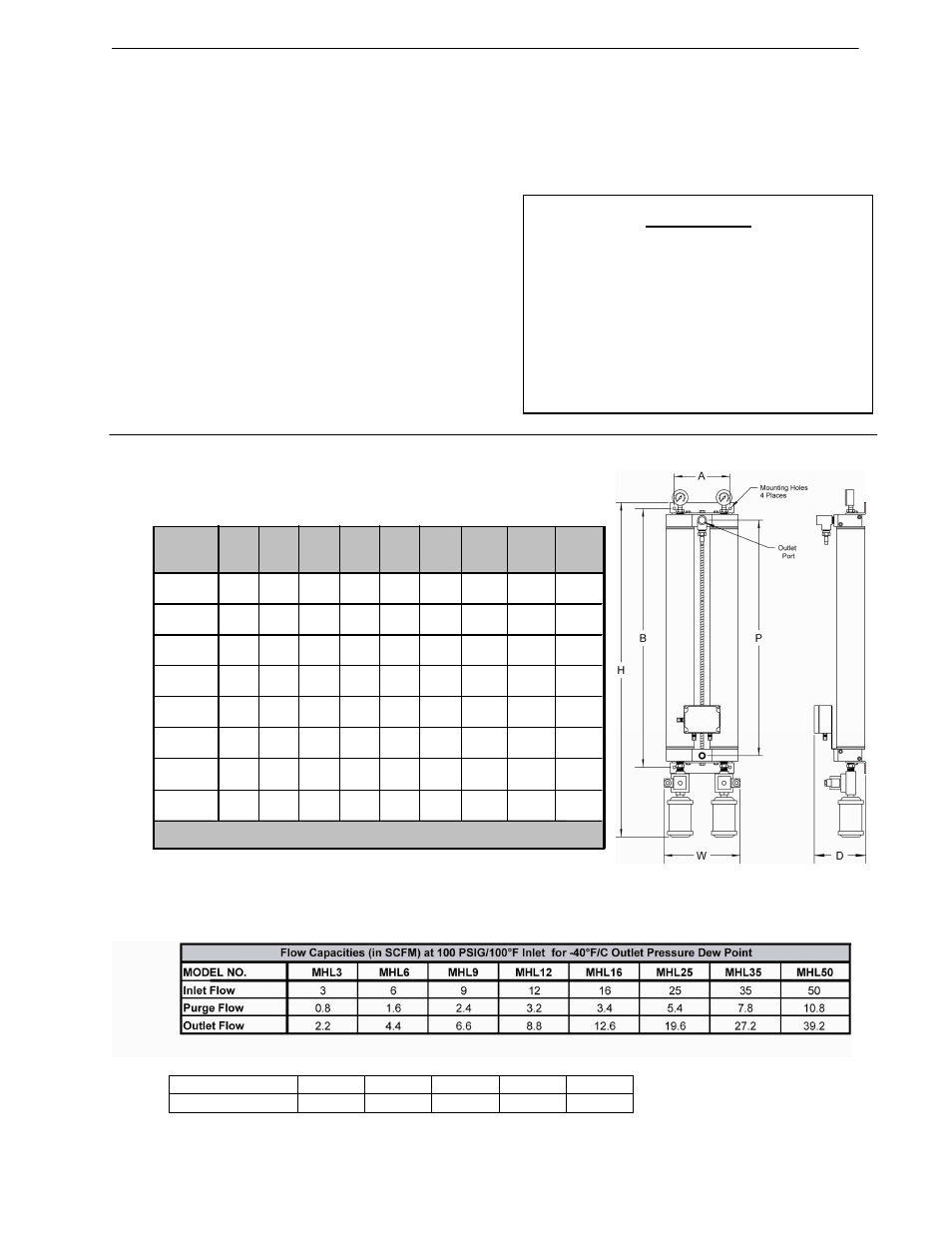
MODEL
H
W
D
P
A
B
PORTS
(npt)
MTG
HOLE
DIA.
WEIGHT
(lbs)
MHL3
13.6
7.4
5.2
9.3
5.8
2.8
3/8
8
MHL6
18.2
7.4
5.2
13.0
5.8
2.8
3/8
0.3
9
MHL9
17.3
7.4
5.2
12.1
5.8
2.8
3/8
0.3
10
MHL12
20.1
7.4
5.2
14.9
5.8
2.8
3/8
0.3
11
MHL16
33.0
9.5
6.5
20.7
7.0
23.6
1/2
0.4
29
MHL25
41.9
9.5
6.5
29.5
7.0
32.5
1/2
0.4
34
MHL35
39.3
10.0
7.0
26.5
9.0
30.1
1/2
0.4
59
NOTE: MHL16-MHL35 dryer shown with bracket top and bottom. MHL3-MHL12 has single 4-hole bracket.
Dimensions shown in inches.
0.3
MHL50
47.4
10.0
7.0
33.5
9.0
37.1
1/2
0.4
65