Page 2, 1 model number coding, 2 serial number coding – Van Air Systems MHL3-MHL50 User Manual
Page 2: 3 description of operation
Van Air Systems MHL-Series Desiccant Air Dryer Operations and Maintenance Manual
Page 2
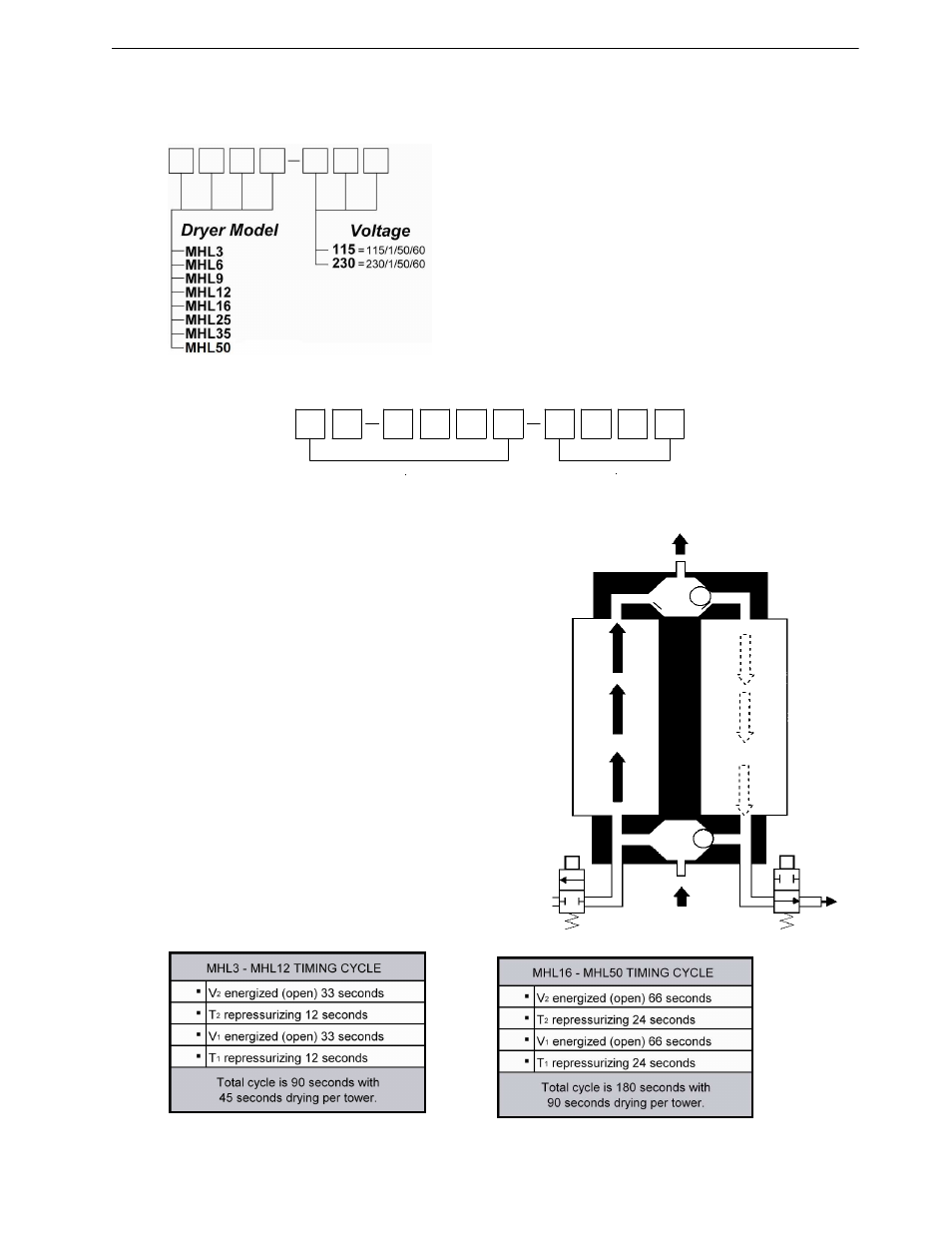
DRY OUTLET AIR
TOWER T
2
REGENERATING
(PURGING)
TOWER T
1
DRYING
INLET AIR
VALVE V
1
CLOSED
VALVE V
2
OPEN
WET INLET AIR
SHUTTLE VALVE
WITH
FIXED ORIFICE
MONTH/YEAR OF MANUFACTURE
SERIAL #
SECTION 1 GENERAL INFORMATION
1.1
MODEL NUMBER CODING
Note: Tower Pressure Gauges & outlet Moisture
Indicator are standard equipment.
1.2
SERIAL NUMBER CODING
1.3
DESCRIPTION OF OPERATION
The MHL-SERIES Air Dryers use the pressure swing adsorption
method of drying compressed air. This requires two identical
towers containing beds of hygroscopic desiccant.
Incoming wet air enters the dryer through a shuttle valve where it
is directed to the bottom of the tower containing dry desiccant.
The desiccant in this tower removes 99.7+% of the water vapor
from the air when operated at catalog conditions. The dried air
leaving the top of the tower is directed to the outlet through a
second shuttle valve. In this outlet shuttle valve a built-in orifice
allows a portion of the dried air to flow into the other tower being
regenerated. The orifice reduces the high pressure air down close
to atmospheric pressure which lowers the dew point of the dried
air even further.
The tower being regenerated/purged of moisture is connected to
an energized solenoid valve for a controlled period of time. The
electrical signal to the solenoid is monitored by an LED light on the
solid state timer. After the desiccant is regenerated, the timer de-
energizes the solenoid valve. Air continues to flow through the
orifice to repressurize the regenerated tower to line pressure. The
middle light on the timer indicates the repressurization function.
Next, the timer opens the valve on the tower containing the wet
desiccant. This shifts the shuttle valves, and the tower with the
wet desiccant is regenerated while the other tower continues to dry
the air. Examining the flow schematic to the right demonstrates
the dryer process operation.