Van Air Systems D12-D36 User Manual
Page 5
PAGE 5
The drain line of the dryer can be remotely piped . DO NOT connect
the drain line to a pressurized line. Make sure that the line is vented
to atmospheric pressure. Any remote drain piping should be of the
same size and on the same level or lower than the drain valve.
When installing the drain line, make sure that the discharge end of the
line or valve is directed away from people and equipment.
2.2-E OPTIONAL AUTOMATIC DRAIN VALVE
The MDV-400I drain valve is recommended, other materials,sizes,
and voltages are available . Contact your local VAN AIR representative
to order.
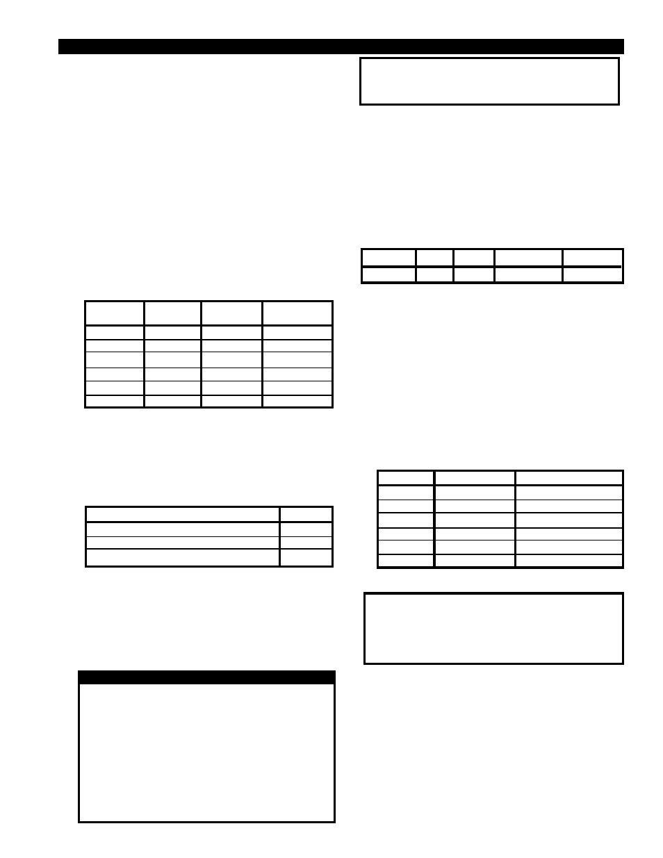
MODEL
VOLT
SIZE
MATERIAL
PART NO.
MDV-400I
115
1" NPT BRASS
39-2411121
Complete the automatic drain valve installation as shown in
FIGURE 2 and outlined in the instructions supplied with the drain.
The drain line can be remotely piped, follow the precautions as
outlined in Section 2.2-D.
2.2-F AFTERFILTER
The installation of an afterfilter prevents any accidental flow of
materials from the dryer into the downstream piping.
The afterfilter may be installed before or after the outlet isolation
valve. If the afterfilter is installed before the isolation valve, the filter
can be isolated from the air system when the dryer is isolated for
maintenance.
Below is a chart of VAN AIR recommended filters. Contact your local
VAN AIR representative to order.
IMPORTANT
The drain solution may contain lubricants. Comply with all
applicaple regulations concerning the disposal of these
chemicals.
2.2-A INLET AND BYPASS PIPING
Using Figure 3 as a reference, make the necessary piping
connections into the dryer.
Inlet and outlet isolation valves should be installed on the dryer.
These valves will aid in the start up and shutdown of the dryer. A
bypass valve and piping should also be installed. This will allow
the dryer to be taken off stream without interrupting the air system.
2.2-B OPTIONAL PRESSURE RELIEF VALVE
A pressure relief valve should be installed to conform to OSHA
safety standards. Refer to OSHA Standard Section 1910.169,
paragraph b, subparagraph 3 and any other federal, state or
local codes concerning pressure vessels.
A coupling was provided on the upper back side of the vessel for
installing the relief valve. A bushing will be necessary to reduce
the coupling to the valve inlet size. Reference FIGURE 3 for
location.
Listed below are the recommended relief valves available for
each dryer. Contact your local Van Air representative to order.
VALVE SIZE
1/2" NPT
1/2" NPT
3/4" NPT
3/4" NPT
1" NPT
1-1/4" NPT
VALVE
PART NO.
14-1462
14-1462
14-1810
14-1800
14-2204
14-2203
DRYER
CONN. SIZE
1" NPT
1" NPT
2" NPT
2" NPT
2" NPT
3" NPT
DRYER
D-12
D-16
D-20
D-24
D-30
D-36
2.2-C OPTIONAL GAUGE INSTALLATION
A coupling was provided on this dryer for the installation of a
gauge.
Three gauges are available for this dryer from your Van Air
representative.
Thread the gauge kit into the coupling provided on the lower, front
side of the vessel as shown in FIGURE 3.
GAUGE KITS
PRESSURE
TEMPERATURE
COMBINATION PRESSURE/TEMPERATURE
PART NO.
29-0252
29-0326
29-0200
NOTE: For dryer models D-12 through D-20 only, the gauge
coupling can be used for the installation of a high level alarm
instead of a gauge.
2.2-D MANUAL DRAIN VALVE
A 1" NPT brass ball valve was shipped separately with the dryer.
Install the valve on the drain line. Reference FIGURES 3 & 4 for
location.
CAUTION
DO NOT CONNECT THE DRAIN TO A PRESSURIZED LINE.
DO NOT INSTALL THE DRAIN LINE IN THE DIRECTION OF
PEOPLE AND EQUIPMENT. WHEN THE DRYER IS DRAINED
THE DRAIN SOLUTION WILL BE DISCHARGED UNDER
LINE PRESSURE. POINTING THE DRAIN IN THE DIRECTION
OF PEOPLE AND EQUIPMENT MAY RESULT IN INJURY
AND DAMAGE.
DO NOT INSTALL A FLOAT TYPE OR SOLENOID TYPE
DRAIN ON THE DRYER. THE DRAIN SOLUTION WILL
CAUSE THESE TYPES OF DRAINS TO FAIL, THUS
RESULTING IN FLOODING OF THE DRYER.
DRYER
D-12
D-16
D-20
D-24
D-30
D-36
FILTER
F200-100-1-B
F200-150-1-B
F200-265-1-1/4-B
F200-400-2-B
F200-600-3-B
F200-800-3-B
DEL-P GAUGE
PD-5
PD-5
PD-5
PD-5
PD-5
PD-5
2.2-G DESICCANT INSTALLATION
IMPORTANT
This dryer was shipped WITHOUT the desiccant installed.
The desiccant MUST BE INSTALLED before using the dryer
THE USE OF CHEMICALS OTHER THAN VAN AIR DESICCANT
WILL VOID THE WARRANTY ON THE DRYER.
The procedures for filling the dryer with desiccant are outlined in
Section 4.4 of this manual.
2.2-H HIGH LEVEL ALARM HLA-120 (P/N 26-3667)
The HLA120 high level alarm is designed to alert personnel that the
drain solution in the dryer has reached an unacceptable level. A
coupling is provided on the dryer models D-24 through D-36. For
dryer models D-10 through D-20 the gauge coupling can be used
to install the alarm instead of a gauge. Contact your local VAN AIR
representative to order.
Install the HLA120 high level alarm in the coupling as shown in
FIGURE 3 and as outlined in the instructions supplied with the
alarm.
SECTION 2
INSTALLATION