Dismantling & assembly instructions, Safety rules when using a die grinder, Reassembly – Universal Air Tools UT1075K User Manual
Page 2
Operating
Select a suitable mounted point that has a free running speed
higher than the maximum running speed marked on the tool.
Make sure that the diameter of the shank exactly matches the
diameter of the collet mounted in the grinder. There are three
standard sizes of collet available for use with this grinder, i.e.
(1) - 1/8" (0.125ins)(3.175mm)
(2) - 1mm (0.039ins)
(3) - 3mm (0.118ins)
Never try to force a 1/8" diameter shank into a 3mm collet.
Never try to close a 1/8" diameter collet to secure a 3mm
shank. Always match correctly the shank size to the collet size.
If uncertain, have parts
measured by a competent
person.
Push the shank as far as
possible into the collet and
tighten the collet nut using the
spanners provided on the
collet nut and output spindle.
The shank of the mounted
point may be pulled forward
from the maximum insertion
length but always ensure a
minimum gripping length of
not less than 10mm - See
Figure 2.
Be aware that the allowed running speed of the mounted point
is lowered because of an increase in the length of the shank
between the end of the collet and the body of the mounted
point. This distance is shown in Diagram 2 as "LO" and is called
the overhang. The information with respect to mounted point
size, permissible running speed and reduction in running speed
due to an increase in overhang is available from the supplier of
the mounted point.
If the increase in overhang for access reasons takes the
permissible running speed of the mounted point below the free
running speed of the grinder select a smaller diameter mounted
point.
The fitting of the mounted point should be done by a trained
operator.
When first starting the grinder with a new wheel fitted, the
grinder should not be near other persons and be held in a
protected area, i.e. under a bench and run for a few seconds.
This will protect personnel from possible effects of damage to
the mounted point before it was fitted to the grinder i.e. wheel
breakage.
Always use eye protection and wear protective gloves if there
are sharp edges in the work area. The tool and the grinding
process can create a noise level such that the use of ear
protectors is advised.
If the grinding process creates a dust then use a suitable
breathing mask.
Check that the material being worked will not cause harmful
dust or fumes. If this is so then special breathing masks may be
required.
If the grinder vibrates when first fitting a mounted point or during
operation, remove from service immediately and correct fault
Dismantling & Assembly Instructions
Disconnect tool from air supply.
First, using the appropriate sized Allen wrench, loosen the hex
screw (19) one complete turn and slide off the rear end holder
(20). Then, using the 9mm wrench, unscrew and remove the
extended air supply hose (21) along with the exhaust overhose
(22). Slide off the sliding knob assembly, complete with O-Rings
(16), (18), air regulator and sliding knob (17). O-Rings (16, 18)
may then be removed from inside air regulator and by pushing
down on air regulator, it may be removed from
sliding knob (17). Unscrew air inlet assembly,
consisting of hose plug (14), pin (15) and air
intake steel tube (13) from body (12). Pin
(15) and air intake tube (13) may then be
removed from hose plug (14).
Using collet wrenches supplied, unscrew collet (2) from rotor
(6). Using a special tool (spanner wrench)with 2 pins, unscrew
lock nut (1) then the complete motor assembly can be pulled off
from angle housing (11). Remove spacer (3) from rotor (6). To
disassemble motor assembly, with a suitable punch, tap the rear
portion of rotor (6) slightly then separate rear end plate (10), ball
bearing (9), cylinder (8), rotor blades (7), front end plate (5) and
ball bearing (4). Slide off the comfort grip (25) from body (12) by
hands. Grip body (12) slightly in a vise fitted with soft jaws. To
separate angle housing (11) and body (12), provide local heating
to the connection thread portion to soften and break the grip of
the thread locking sealant. Then, unscrew the angle housing
(11) from body (12).
Reassembly
Clean all parts and examine for wear, replacing any worn or
damaged parts. Use only replacement parts obtained from the
manufacturer or an authorized distributor. Lightly coat all parts
with a suitable pneumatic tool lubricating oil and assemble tool
in reverse order.
pour into the intake bushing a 1/5 teaspoonful (1ml) of a
suitable pneumatic motor lubricating oil preferably incorporating
a rust inhibitor. Reconnect tool to air supply and run tool slowly
for a few seconds to allow air to circulate the oil. If tool is used
frequently lubricate on daily basis and if tool starts to slow or
lose power.
It is recommended that the air pressure at the tool whilst the
tool is running is 90 p.s.i./6.3 bar. The tool can run at lower and
higher pressures with the maximum permitted working air
pressure of 100 p.s.i./7 bar.
Page No 2
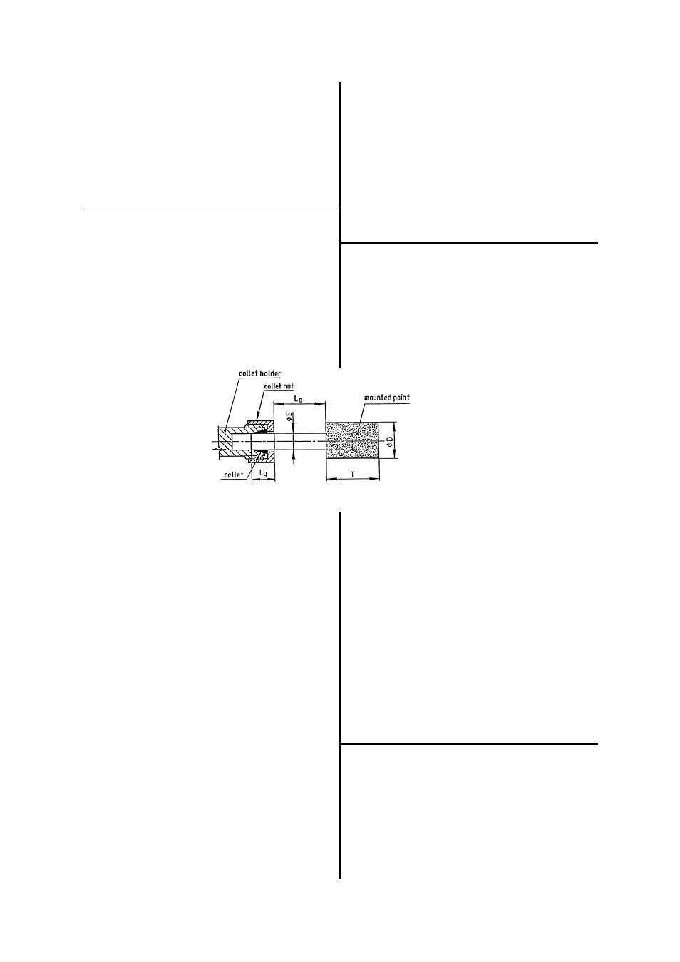
D
= diameter of mounted point
T
= length of mounted point
Lo
= overhang
S
= diameter of shank
Lg
= gripping length
Figure 2. Gripping length of collet and chuck
Safety Rules When Using A Die Grinder
1) Read all the instructions before using this tool. All operators
must be fully trained in its use and aware of these safety rules.
2) Always select suitable abrasive to use with this tool - see
Operating Instructions.
3) Always shut off the air supply to the grinder and depress the
lever to exhaust air from the feed hose before fitting, adjusting
or removing the mounted point.
4) Always adopt a firm footing and/or position before using the
grinder.
before continuing to use.
Do not apply excessive pressure as this will reduce the cutting
efficiency and can bend the shank of the mounted point causing
vibration and the possibility of breakage. Apply light loads to
allow the wheel to cut.
Handle the grinder with care. If the grinder is dropped, carefully
check the mounted point for damage, i.e. cracks, chipping and
start for the first time as for fitting a new wheel i.e. under a
bench.
Never exceed the maximum air pressure. If there is this
possibility always use this grinder with a pressure reducing valve
fitted in the supply line. Your supplier will advise of suitable
equipment.