Dry fit the components before securing, Secure the upper elbow, Fit the straight tube length(s) – U.S. Sunlight 2014ST Rigid Tube Kit User Manual
Page 3: Important: remove the protective film
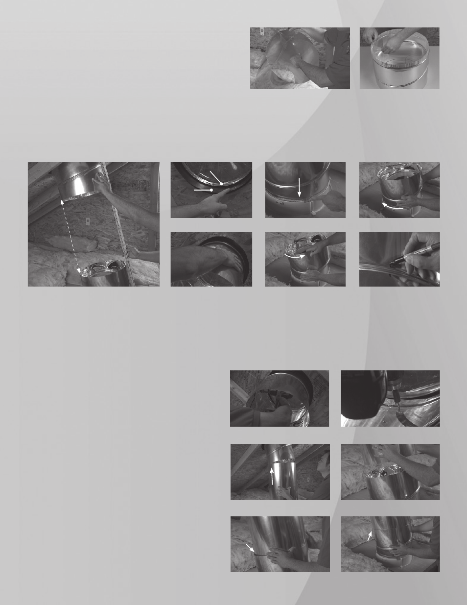
Dry fit the components before securing
It is important to “dry fit” the parts of the Rigid Tube Kit as close as possible to their final angles before securing. The
best method is to try to line up the Upper Elbow to the Lower Elbow by changing the tilt and rotation of each as they are
sitting in the Dome Flange and Diffuser Housing. The requirement is that they line up as much as possible prior to insert-
ing the straight tube length(s). If you can, check with a yard stick or long level along both edges as shown in
(fig. 20).
fig. 20
Tilting the Elbow
fig. 24
Rotating
the base
fig. 25
Step 11
The Upper Elbow fits inside the flange and rests against the retaining ring.
(fig. 21) Fit the Upper Elbow into the flange and adjust the angle
to point at the Diffuser Housing
(fig. 22) The crimped edge of Lower Elbow fits into the Diffuser Housing and rests on the three retaining band
posts
(fig. 23) Both elbows adjust the same way as shown in (fig. 24 & 25). When satisfied with the initial adjustments, draw a registration
mark to indicate the desired angles.
(fig. 26)
fig. 21
fig. 22
fig. 23
fig. 26
Secure the Upper Elbow
Step 12
With the Upper Elbow held securely against the retaining ring
in the final desired position, drive a Mounting Screw through
one of the pre drilled holes into the Flange.
(fig. 27) Continue
until all three screws are installed.
(fig. 28)
fig. 27
fig. 28
Fit the Straight Tube length(s)
Step 13
As you fit the Straight Tube(s) into position, the larger opening
of the tube(s) should always be at the top and should fit over
the preceeding tube or elbow
(fig. 29) and then fit inside the
bottom component as you work your way down the installa-
tion.
(fig. 30 & 31) Make final small adjustments to the Lower
Elbow if necessary. Overlap each component by no less than
1” and try to minimize any protruding areas to create smooth
transitions between each piece.
(fig. 32)
fig. 29
fig. 30
fig. 31
fig. 32
Fit on the outside
of the top
components
Fit on the inside
of the bottom
components
Adjust for a tight,
smooth transition
IMPORTANT:
Remove the protective film
Before beginning the fitting and installation, peel off all of the
protective film on the inside of each component. Otherwise,
you won’t be able to peel the film after the tube is sealed.
(fig. 18 and 19).
fig. 18
fig. 19
Flange
Retaining Ring