Build the support structure, Mounting the light kit (flex tube), Step 6 – U.S. Sunlight 2014ST Light Kit User Manual
Page 3: Step 7, Step 8 (flex tube)
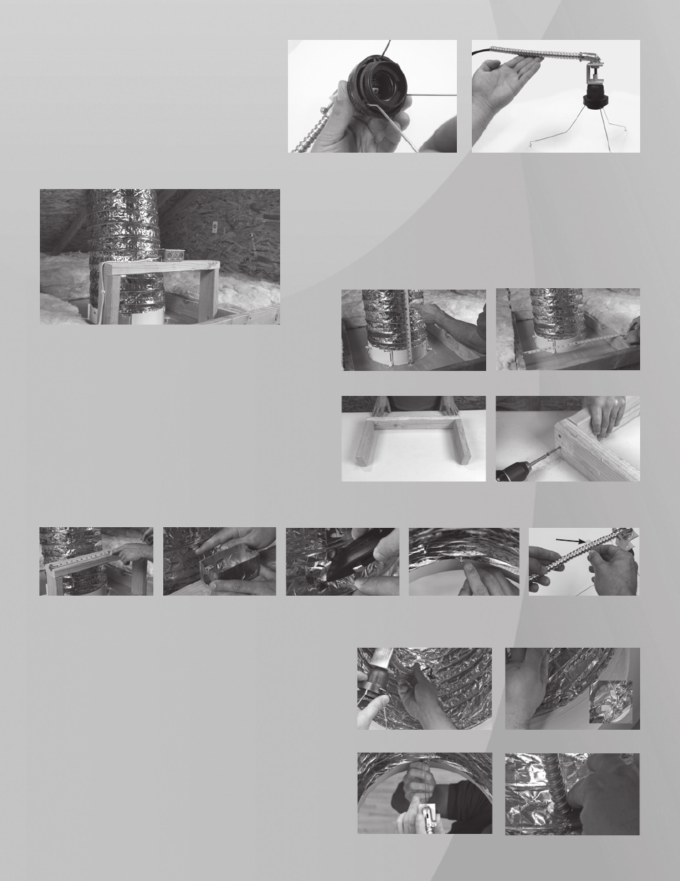
Step 6
Insert the 3 Legs into the slots on the bottom of the
Socket Assembly as shown in (fig. 18) Press them in
firmly to seat properly, once fully seated,they should
not come out easily. Once you complete this step,
the light Kit is ready to install into your SkylightTube.
(fig. 19)
fig. 19
fig. 18
Build the Support Structure
Step 7
In this example, we will build the structure to fit between the
2 ceiling joists. First, measure the distance between the inner
edges. (fig. 21)
Cut a section of the 2 x 4 to that length, then cut 2 pieces to
11” to form the sides. (fig. 22)
Then fasten together with the 3”deck screws. (fig. 23)
The Support Structure can be configured as necessary to allow the
flexible conduit and junction box to be supported at the correct height
relative to the Light Kit assembly when it is installed. The requirement
is that the flexible conduit and Junction Box be supported between 12
1/2” to 13 1/2” from the top of the sheet rock.
(fig. 20)
fig. 20
fig. 21
fig. 22
fig. 23
fig. 24
fig. 25
fig. 26
fig. 27
fig. 28
Mounting the Light Kit (Flex Tube)
Step 8 (Flex Tube)
Set the Support Structure in the desired installation position and
find the center on top and mark. (fig. 24) Place the Junction Box
in position over the center and note where the exit point will be
for the flex tube - straight across and level to the center hole on
the box. (fig. 25) Make a cross cut in the material about 3/4” wide
(fig. 26)
From inside the Diffuser Housing, install the 3 Wing nuts
on the existing posts but do not tighten all the way. (fig. 27) If the
posts are covered with foil tape uncover with Utility Knife.
Remove the protective cover from one of the Reinforcement
Rings and place onto the Flexible Conduit, adhesive side out.
(fig. 28)
Then guide the cord and Flexible Conduit through the
cross cut and attach the 3 Legs onto the Wing nut posts and
tighten firmly. (fig. 29, 30 & 31) You may need to adjust the
Socket and Connecting Bracket slightly to allow the Legs to fit.
Once you have tightened the Wing nuts press the Reinforcement
Ring onto the Flex Tube (fig 32)
fig. 29
fig. 30
fig. 31
fig. 32
Adhesive side