Remote diagram, Setting the remote after the controller module, Installing solar controller – U.S. Sunlight SC5-R Solar Controller Remote User Manual
Page 2
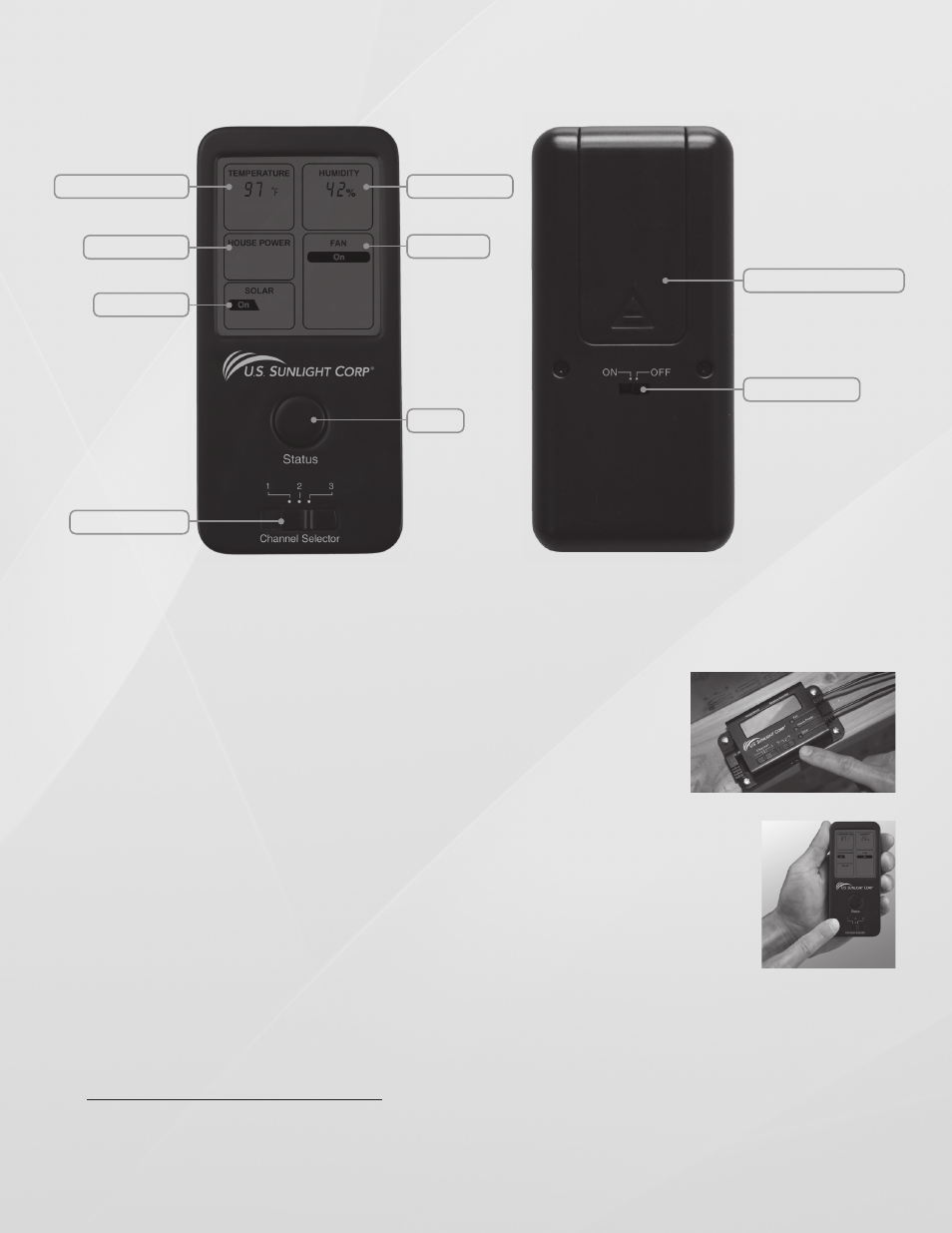
Attic Temperature
Attic humidity
Thermo Switch
Battery Compartment
Fan Mode
House Power
Solar Power
Status
Channel Switch
Thermo Switch
Copyright 2012 U.S. Sunlight Corp, Inc. SC5-R C01 ver 1
Remote Diagram
Installing Solar Controller
If your Solar Controller came bundled with an attic fan, install the fan first following the instructions included for that model
of fan. When the installation of the fan is complete, install Solar Controller. Note that Solar Controller is designed to work
with U.S. Sunlight Solar Attic ventilation products. The Controller Remote will only work as an accessory to the Controller
Module, refer to model SC5-M for this component. DO NOT ATTEMPT to connect Solar Controller to other solar fans.
Setting the Remote after the Controller Module
1. The Controller Box has 2 slide switches, the one on the left is for selecting the Radio
Frequency (RF) channel and the one on the right is for selecting the temperature
readout in Celsius (°C) or Fahrenheit (°F). Align the RF channel (choice of 1, 2 and 3)
of the Remote with the Controller Module. Both of them must be on the same channel
in order to send and receive signals. Select the desired temperature readout.
(fig 1a & 1b)
2. Remove the back panel of the Remote. Insert 2 AAA batteries (included) in the battery
compartment. Replace the back panel of the battery compartment.
3. Test the Remote by pressing the Status button once. This will establish the connection
between the Controller Module and Remote. You will hear a “beep” every time the Status
button is pressed. This verifies the Remote and Controller Module RF signals are aligned.
If there is not a beep, check that the RF channel selector is set to the same channel. If
there is still no beep, move both devices to an alternative channel and retry.
fig. 1b
fig. 1a