Rt2000 s, Osp) – Triton RT2000 Installation Manual User Manual
Page 46
46
RT2000 S
ERIES
- S
ITE
P
REPARATION
AND
I
NSTALLATION
G
UIDE
I
NSTALLING
THE
O
PERATOR
S
ERVICE
P
ANEL
(OSP)
The panel is shipped in the auxilliary
box. Follow the procedures for install-
ing the OSP.
1.
Carefully inspect the panel for any
shipping damage and report any
damage immediately to the
shipping company. Refer to the
warranty information in the User
or Service manual (as applicable)
for information about reporting
shipping damage.
2.
If the unit is ON, enter
Management Functions >
System Parameters > Shut
Down the Terminal. When
prompted on the screen, open the
sleeve cabinet door and turn the
power switch on the power supply
to the OFF (0) position.
3.
The mounting bracket for the OSP
is located in the upper right corner
as shown in Figure 1. There are
three (3) mounting studs visible.
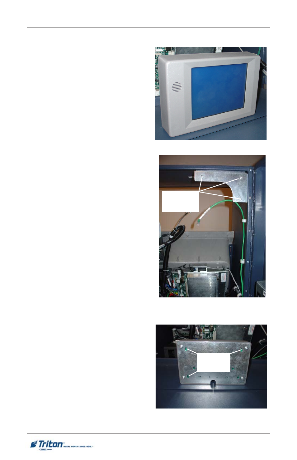
4.
The back of the panel has four (4)
mounting slots (3 will be used).
(Figure 2)
5.
Mount the OSP so that the data
cable will be connected on the
bottom of the panel (Figure 3).
The Operator Service Panel is a touch-
screen panel that provides convenient
user-access to cassette close and replen-
ishment functions from inside the facil-
ity. It also provides diagnostic func-
tions, ability to reset errors, and termi-
nal shutdown.
Operator Service Panel
Figure 1. Mounting bracket.
Figure 2. Rear view of OSP.
Mounting
studs
Data cable connector
Mounting
slots