Connecting ac power and telephone line – Triton RT2000 Installation Manual User Manual
Page 43
43
P
OWER
AND
D
IAL
-
UP
C
OMMUNICATION
Figure 2. Install snap bushing.
3.
Install the supplied snap bushing
into the access hole that carries the
power and phone cords. See Figure
2 for an example that shows the
snap bushing on the access hole.
4.
Plug the AC power plug into the
wall outlet.
5.
Plug the phone cord into the wall
mounted modular phone jack.
Connecting AC Power and
Telephone Line
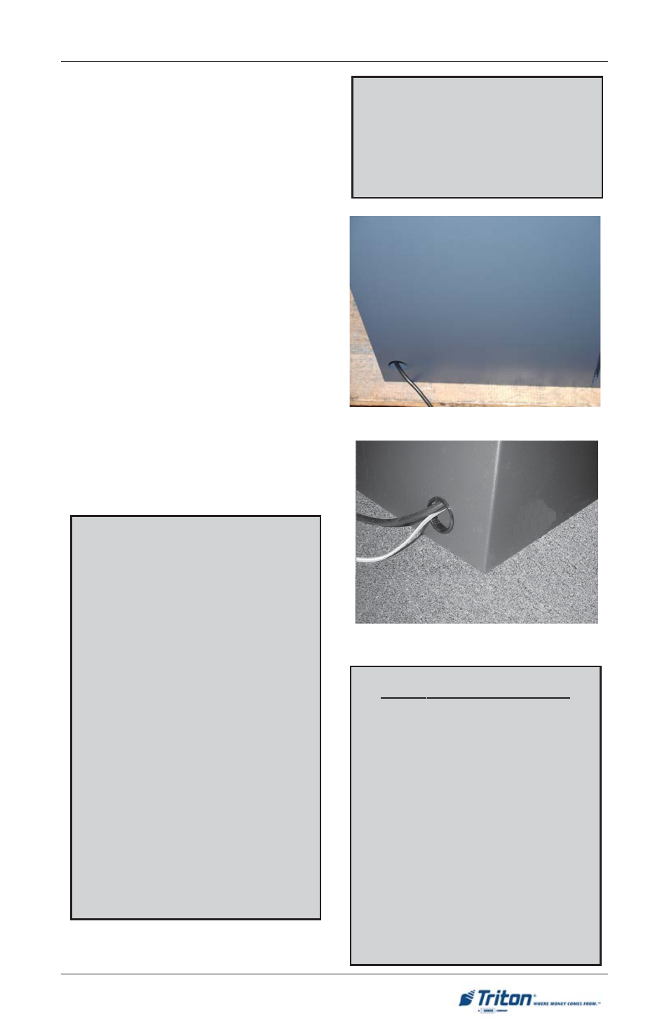
Figure 1. Left side access hole shown.
*** WARNING***
This unit may be equipped with
more than one power cord. DIS-
CONNECT ALL POWER
CORDS PRIOR TO SERVIC-
ING!
1.
Ensure the power and phone cables
are routed through the cable clips
located in the vault cabinet.
2.
Route the AC power cord and the
phone cord through either of the
front right or left side access holes
(as applicable) in the security
cabinet, as shown in Figures 1.
Power Outlet Accessibility
Whether you are installing a new
outlet, or plan to use an existing
outlet to supply power to the ATM,
make sure the following require-
ments are met:
1.
The outlet is located near the
cabinet.
2.
The outlet is easily accessible.
3.
Access to the outlet will not be
blocked once the cabinet is in-
stalled!
Power Supply Cord
Specifications
For European applications, the power
supply cord must conform to the fol-
lowing specifications:
1.
Two-conductor with physical
earth ground.
2.
IEC 320 molded connector on
one end and molded plug on the
other end.
3.
Certified for country of
installation.
4.
Rated minimum H05VV-F with
minimum 0.75 mm2 (except
where specfic countries require
1.0 mm2) conductors.
5.
Maximum length: 3 meters.