Tilton 40000-Series (98-095-6) User Manual
Page 2
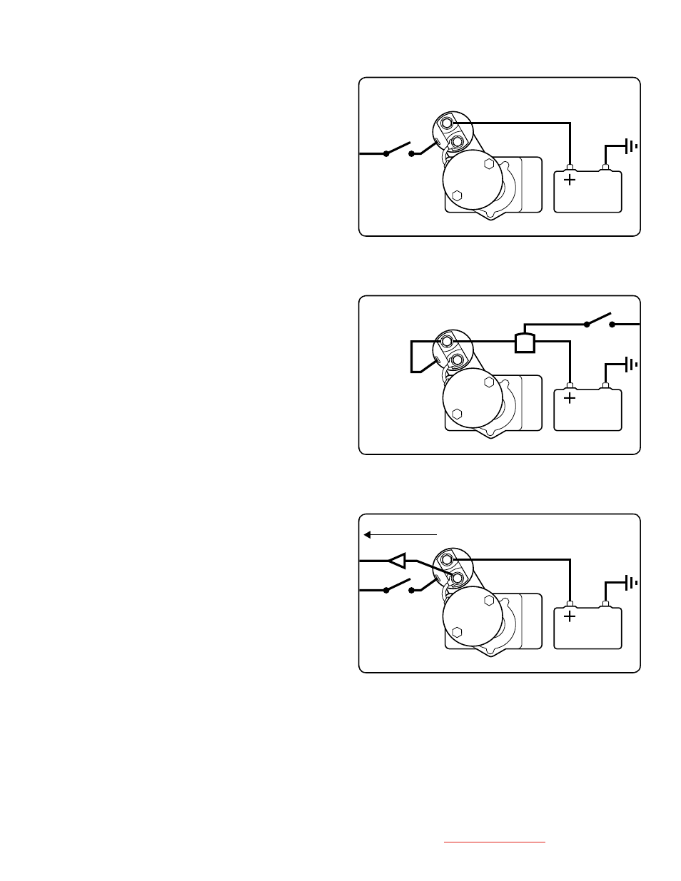
Distributor
10 Amp Diode
Battery
Switch
solenoiD configurations
Standard (General Motors)
Figure 4
Connect the positive battery lead to the unused post on the
solenoid. Connect the smaller switch lead to the spade terminal
on the solenoid.
Remote Solenoid (Ford Or Chrysler)
Figure 5
If your vehicle has a remote solenoid, connect the large positive lead from
the remote solenoid to the unused post on the starter solenoid. Use the short
jumper wire (provided) to connect the spade terminal to the same starter
solenoid post as shown.
Ignition Resistor Bypass
Figure 6
If your vehicle requires an ignition resistor bypass, you can connect the exist-
ing bypass wire to the lower stud IF a 10 amp. diode is placed in the wire to
prevent feedback voltage from reaching the starter. Note: Resistor bypass was
used only on some GM models (late-60’s, early-70’s) and applies to cars still using
the OEM distributor and point-type ignition. If you are running an aftermarket
distributor, you will not connect the extra wire (usually purple) to anything.
Figure 4
(Standard Connection)
Figure 5
(Remote Solenoid Connection)
Figure 6
(Ignition Resistor Bypass)
Jumper
Wire
Solenoid
Switch
Battery
Starter
Switch
Battery
Tilton Engineering, Inc. 25 Easy Street • PO Box 1787 • Buellton, CA 93427 • www.tiltonracing.com