Wiring diagram, Important, Wiring diagram for interface – SANDPIPER RuppTech Stroke Counter/Batch Control User Manual
Page 7
Batch Control/Stroke Counter
Page 7
Batch-sc-rev0611
520-180-000 3/02
Batch Control / Stroke Counter
Page 7
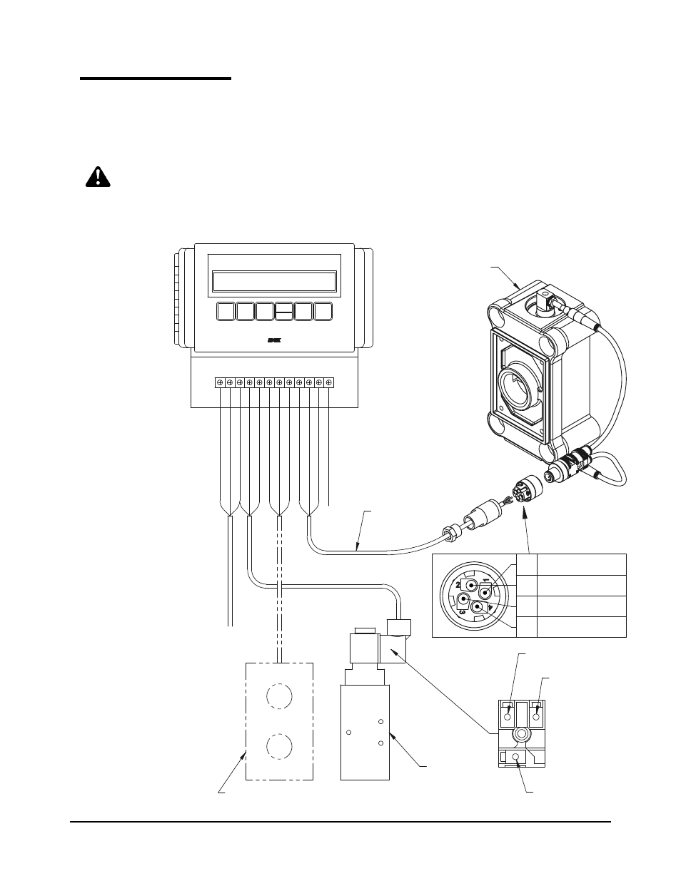
Wiring Diagram
Connecting the control box to other
system components.
®SandPIPER, RuppTech and Warren Rupp are registered tradenames of Warren Rupp, Inc.
©2002 Warren Rupp, Inc. All rights reserved.
IMPORTANT!
If installing other RuppTech components,
such as the Pulse Output Kit or Solenoid Kit,
please refer to the separate service pages supplied
with the items.
NOTE: Use a momentary con-
tact switch when using a remote
start/stop control.
Wiring Diagram for Interface
with 249-006-000 Batch Control / Stroke Counter (Non-Hazardous Location)
SandPIPER Air Valve
Mounted to Pump
Power Input
#22 AWG Cable
Terminal #1
Neutral (Positive)
3rd Terminal
for ground
Terminal #2
Power (Negative)
2
1
Customer Supplied
Remote Control
Momentary Switch
Solenoid
Air Valve
Output Channel #2
4
3
2
1
(+) Common
(-) Ground
Output Channel #1
GR
OUND
CHASSIS GR
OUND
PR
O
XIMIT
Y SENSOR INPUT(S)
24VDC
ST
OP SWIT
CH
100-120V
AC
ST
AR
T SWIT
CH
RELA
Y OUTPUT C
OMMON
RELA
Y OUTPUT (+)
100-240V
AC
COMMON GR
OUND
NEUTR
AL
POWER 100-240V
AC
Stroke counter/Batch Control
STOP
RESET
PRESET
COUNT
DIGIT
SELECT
TOTAL
COUNT
START
IDEX CORPORATION
INCREASE
DIGIT
WARREN RUPP PUMP CONTROLS