Wiring diagram, Caution!!! remove power before setting, Important – SANDPIPER RuppTech Stroke Counter/Batch Control User Manual
Page 6
Batch Control/Stroke Counter
Page 6
Batch-sc-rev0611
520-180-000 3/02
Batch Control / Stroke Counter
Page 6
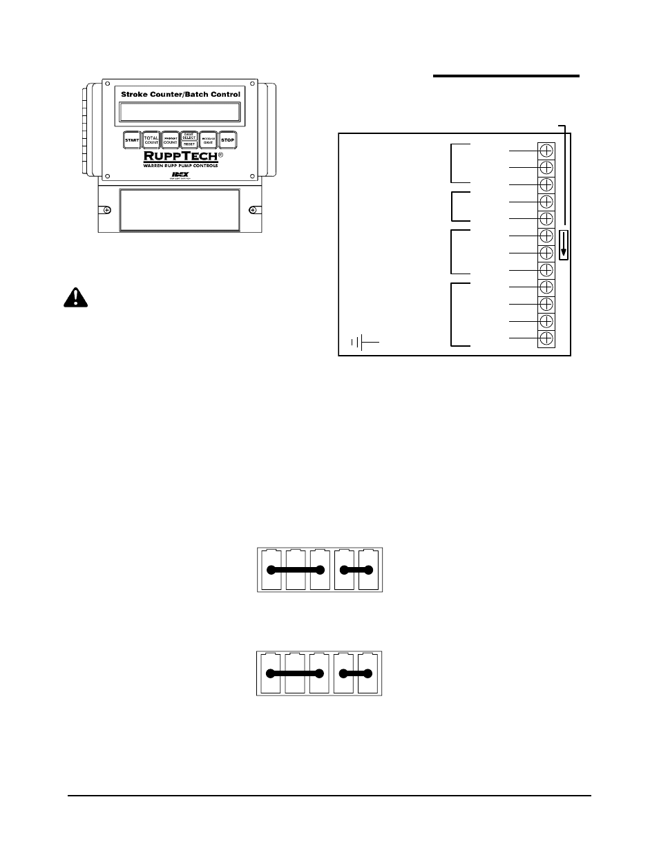
Wiring Diagram
IMPORTANT!
If installing other RuppTech
components, such as the Pulse Output Kit
or Solenoid Kit, please refer to the separate
service pages supplied with the items.
Wiring Diagram 249-006-000
+
c
L1
L2
COMMON GROUND
RELAY OUTPUT
START SWITCH
120VAC
STOP SWITCH
+V
PROXIMITY SENSOR INPUT
GROUND
CHASSIS GROUND
100-120/240VAC
Jumper
Direction Arrow Refers 120V
220V 120V
This device is factory set for 90-130VAC, 50/60Hz.
For 200-230VAC, 50/60Hz, remove and rotate the jumper plug as show below.
CAUTION!!! REMOVE POWER BEFORE SETTING!!!
Factory Set
90-130VAC
ARROW
Optional
220VAC
ARROW
Replace fuse with Type 3AG/250V, .5A, or equal, Fast Blow ONLY.