SANDPIPER RuppTech Stroke Counter/Batch Control User Manual
Page 2
Batch Control/Stroke Counter
Page 2
Batch-sc-rev0611
520-180-000 3/02
Batch Control / Stroke Counter
Page 2
Programming for Accuracy:
Batch Control Mode
Published pump performance is the starting
point for programming the batch controller.
But your actual system performance must be
verified, to achieve the expected 1 to 3% accu-
racy. This is accomplished through initial test
runs and measurement. On the following page
you will find an example showing the recom-
mended sequence for verifying your system’s
actual performance.
Batch Controller Mode
In this mode, the Control can be programmed to transfer a fixed
volume of product. A Preset Count is programmed into one of the ten
program storage areas (P0-P9). This tells the pump how much product
will be transferred (one “batch”) each time the Control is activated.
There is a START switch and a STOP switch mounted on the front of
the Control for this purpose. There is also an internal connection for
remote START and STOP switches that a customer may want to install.
NOTE: Use a momentary contact switch when using a remote
start/stop control.
In the batch control mode, the Total Count function remains active.
At the end of a shift (several programmed “batches”) the customer can
reference the total stroke count or transferred volume of fluid handled
during the time period. All other basic functions remain active (Scale
Factor, Reset Total Count), as well as advanced functions (i.e. Preset
Count, multiple program storage, Reset Preset Count) which are
explained later in this manual.
The Batch Controller Mode also uses the Pulse Output Interface to
receive a count from the pump. It requires an electric solenoid valve
(available from Warren Rupp) in the air line to the pump. This valve is
a normally closed, 3-way, AC voltage (standard control) unit, and is
purchased separately. The solenoid starts and stops the pump through
the control. The pump is stopped by turning off the air supply to the
pump, after it has transferred a batch, volume or count programmed
into the control. The pump is restarted by turning on the air supply to
the pump.
In this Mode of operation the pump will start pumping when it
receives a signal from the control. This opens the valve in the air line.
The signal can be activated from the control mounted switch or from a
remote signal. The pump will stop automatically once the Preset Count
has been reached. The pump can also be stopped mid-operation,
using the control mounted STOP switch or from a remote STOP signal.
When restarted, the pump will continue the operation from the point
of interruption.
If power to the control is lost during operation, the pump will stop.
When power is restored, the control resets to the P0 program. The
pump will not continue operation without receiving a START signal. This
function is to prevent accidents or product spillage. Before re-starting
the unit, be certain to select the program which was interrupted. When
the pump has completed a cycle, the Preset Count display will flash
until it is activated again. When reactivated, the display will reset and
restart the count from the Preset Count selected. If the count is stopped
mid-cycle from the STOP switch, the display will not flush.
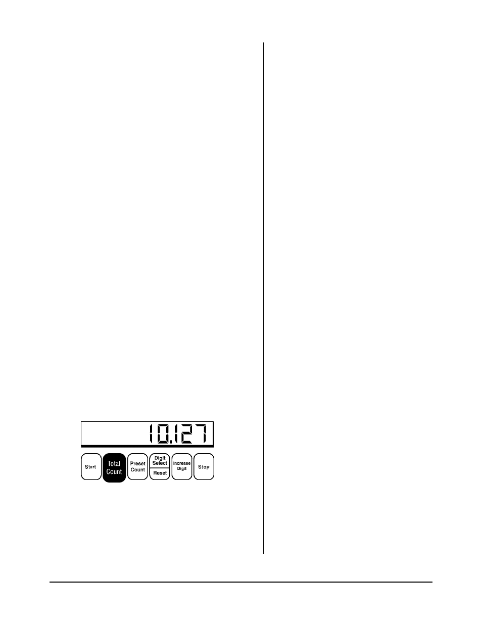
When viewing the PRESET COUNT, a flashing LED display means
the pump was stopped after COMPLETING the programmed
cycle.
If the STOP button is used to stop the operation mid-cycle, the
display will not flash. When reactivated, the pump will continue
the cycle from the point of interruption.