SANDPIPER RuppTech Stroke Counter/Batch Control User Manual
Stroke counter/batch control, Service and operating manual
Batch Control/Stroke Counter
Page 1
Batch-sc-rev0611
520-180-000 3/02
Batch Control / Stroke Counter
Page 1
A General Overview of this Control System
This control functions in two modes of operation:
• stroke counter mode
• batch controller mode
The two modes can be operated together or alone.
The control receives a signal from the diaphragm pump for each
pump stroke. It accomplishes this through a
RuppTech® Pulse Output
Interface mounted on the pump.
RuppTech
®
Pulse Output Interface - (available ONLY
from Warren Rupp, Inc.)
The Pulse Output Interface mounts on the pump and provides
electrical signals to operate the Control. This creates an electrical
interface between the control and the air-powered pump.
Each pump stroke generates a signal through a proximity switch (PNP)
on either end of the air valve. As the air valve reciprocates back and forth
during pump operation, targets on either end of the sleeve and spool
set trigger their respective proximity switches. Each trigger signals the
control to register one count on the stroke counter / batch control unit.
This method provides a positive signal for every pump stroke.
The Pulse Output Interface are designed for easy field installation. The
interfaces are also available factory-installed on new pumps. Pulse Output
Interfaces can be purchased separately from the control unit for those
applications where a process controller is already present in a system.
This provides a direct interface with the pump and the customer’s
system.
Stroke Counter Mode
In this mode, the control keeps a running tally of the total number of
strokes of the pump. The control saves this total until the accumulated
count is reset from the control’s keyboard, or the counter exceeds the
10-digit capacity of the display. The count can be pump strokes (one for
every stroke), or a measure of volume (i.e. gallons, liters, pounds) to
indicate total volume pumped. The stroke count could also be used
to indicate how long the pump has run. This is helpful for preventative
maintenance schedules, or to account for the volumes of fluid being
transported or consumed. The stroke counter function is cumulative,
even if the pump is turned off and on by some means other than the
control. Any time the pump is running and the control is powered, it will
store the total count for future reference.
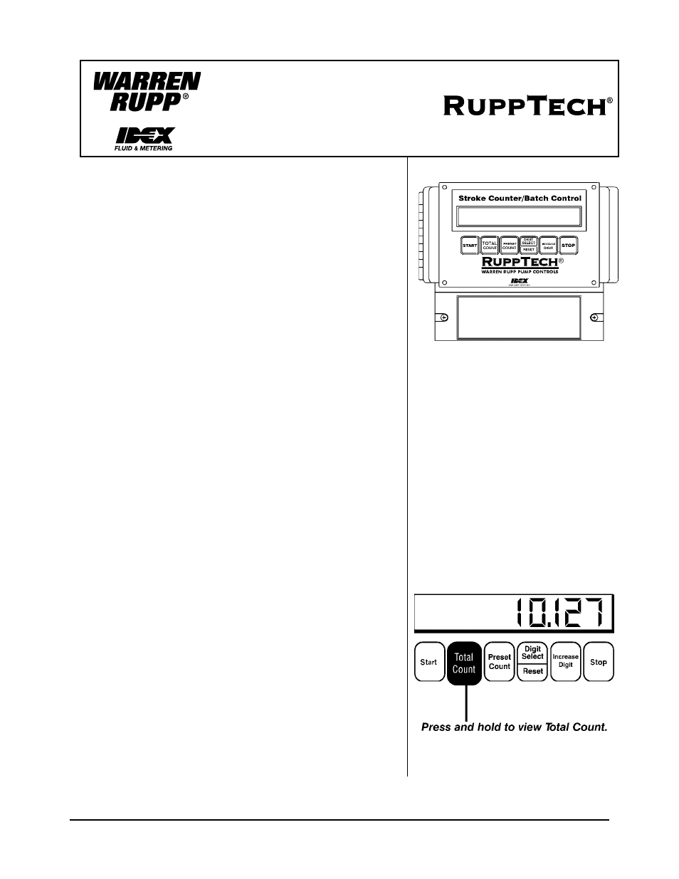
To view the totalized count, push and hold the Total Count button on
the control keyboard. (To extend the life of the LED display, the count
does not display continuously.) Refer to the Programming Instructions
in this manual to set the scale per stroke or reset the count.
Warren Rupp, Inc. A Unit of IDEX Corporation • P.O. Box 1568 • Mansfield, OH 44901-1568 USA • 419 524 8388 Fax 419 522 7867 www.warrenrupp.com
SERVICE AND OPERATING MANUAL
Stroke Counter/Batch Control
249-006-000 • 100-120/240VAC • 50/60
hertz
NEMA 12 Enclosure
Height 6.1” (15.5cm)
Width 6.54” (16.6cm)
Depth 3.46” (8.8cm)
10-digit LED display
4 push buttons for setup
10A relay output for solenoid valve
2 proximity sensor inputs
2 remote on/off switch inputs
Warren Rupp, Inc. A Unit of IDEX Corporation • P.O. Box 1568 • Mansfield, OH 44901-1568 USA • 419 524 8388 Fax 419 522 7867 www.warrenrupp.com