SANDPIPER ELECTRONIC LEAK DETECTOR 032-037-000, 032-043-000 User Manual
Page 2
Electronic Leak Detector-VAC Page 2 eldvacsm-rev0513
Wire Instructions (Schematic)
Warren Rupp does not supply a power cord due to the
many various lengths that may be necessary to get the
appropriate voltage source. We do recommend that a
3-lead wire of 14-gauge minimum be used to hook into
the detection box. One end of the box has a single
7
/
8
"
diameter hole common to electrical boxes. The power
cord should be wired into the box as the schematic
(Figure C) shows. The connection is in the cover area.
Terminals are marked L1 (power), G (ground), and L2
(common). Your detection system should now be ready
for use.
Probe Installation
To install the probe, first back-twist the cable
counterclockwise to avoid wire twist when the
probe is treaded clockwise into the 1/4" NPT tees
or ports. Apply PTFE tape or a small amount of
thread sealant to the threads prior to insertion.
NOTE: When the leak detector is installed on
Models SET1 and SET2, the probes must be fitted
into special boss plug kits. Order one Boss Plug
Kit 475-098-000 per pump.
Used on Models
Electonic Leak
Detector
SB1, SB1½, SB2, SB3
ST1, ST1½, SSB1, SSB2
SET1 and SET2
ET1, ET1½
{
032-043-000
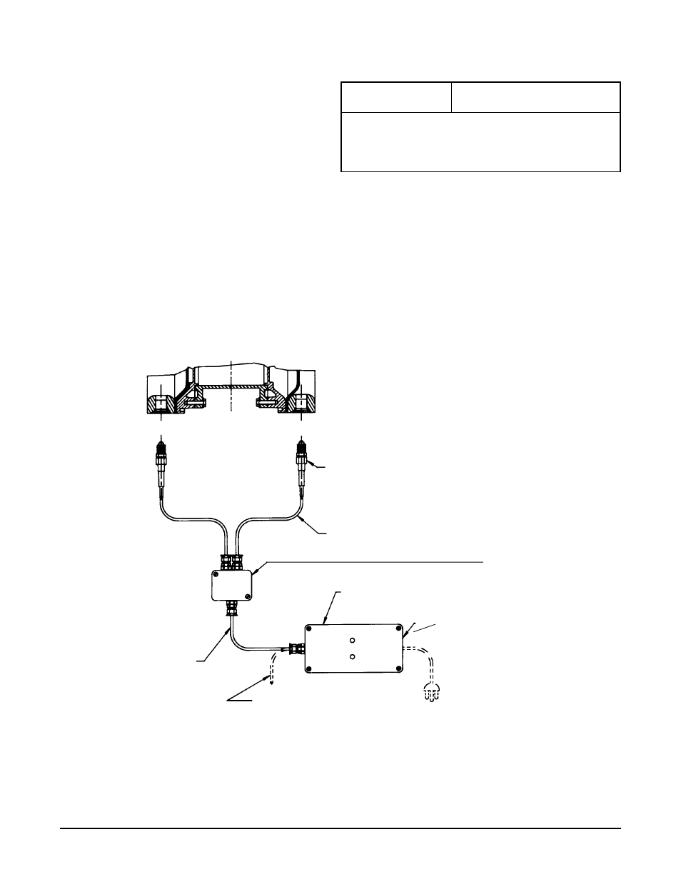
SAMPLE
PUMP
SECTION
PROBE ASSEMBLY
(P/N 628-002-000
(2 required)
DETECTOR CONTROL UNIT
(P/N 249-009-000)
(NEMA 1, 2, 3, 4, 4x, 5, 12 & 13)
FOR WIRING
DETAIL
SEE FIGURE B
POWER CORD
(NOT INCLUDED)
15 ft. lg. 3 LEAD WIRE
(P/N 150-027-000)
WIRING ILLUSTRATION
FIGURE A
POSSIBLE WIRING CONNECTION
FOR ALERT SYSTEM AND/OR
TOTAL SYSTEM SHUT DOWN.
(NOT INCLUDED)
2 ft. lg. 2 LEAD WIRE
ENCLOSURE ASSEMBLY
(P/N 111-002-000)
(NEMA 1, 2, 3, 4, 4x, 5, 12 & 13)
See Wiring Illustration
FIGURE B