SANDPIPER M30 Metallic User Manual
Page 25
m30mdl1sm-rev0713
Model M30 Metallic Page 23
DIAPHRAGM SERVICING
To service the diaphragms first
shut off the suction, then shut off the
discharge lines to the pump. Shut
off the compressed air supply, bleed
the pressure from the pump, and
disconnect the air supply line from the
pump. Drain any remaining liquid from
the pump.
Step #1: See the pump assembly
drawing, and the diaphragm servicing
illustration.
Using a 9/16" wrench or socket,
remove the 16 capscrews (item 10),
and hex nuts that fasten the manifolds
(items 22 & 23) to the outer chambers
(item 14).
Step #2: Removing the outer
chambers.
Using a 11/16" and a 5/8" wrench
or socket, remove the 16 capscrews
(items 9), and hex nuts that fasten the
outer chambers, diaphragms, and inner
chambers (items 15) together.
Step #3: Removing the diaphragm
assemblies.
Use a 1
1
/
16
" (27mm) wrench or six
pointed socket to remove the diaphragm
assemblies (outer plate, diaphragm,
and inner plate) from the diaphragm rod
(item 32) by turning counterclockwise.
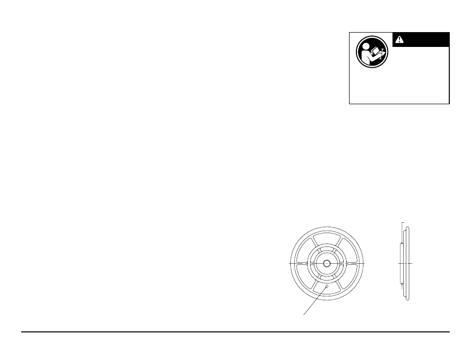
NOTE: To uninstall the diaphragm plates
from the diaphragm, hold the inner diaphragm
plate using one of two methods:
Preferred Method: Place the assembled
plates and diaphragm in a large vise, gripping on
the exterior cast diameter of the inner diaphragm
plate (see the drawing at far right).
Alternate Method: When a larger vise is not
available, insert a 1/4 - 20UNC hex capscrew
or setscrew (standard hardware) into the tapped
hole in the inner diaphragm plate. Insert the
assembled plates and diaphragm into a vise
with the stud from the outer plate and the
1/4 - 20 fastener loosely between the jaws of the
vise (see illustration at right).
Use a 1
1
/
16
" wrench or socket to
remove the outer diaphragm plate
(item 29) by turning counterclockwise.
Inspect the diaphragm (item 17) for cuts,
punctures, abrasive wear or chemical
attack. Replace the diaphragms if
necessary.
Step #4: Installing the diaphragms.
Push the threaded stud of the outer
diaphragm plate through the center hole
of the diaphragm. Thread the inner plate
clockwise onto the stud. Use one of the
two methods for holding the inner diaphragm
plate that was described in prior note in step
#3. Use a torque wrench to tighten the
diaphragm assembly together to 50 ft.
lbs. (67.79 Newton meters). Allow a
minimum of 15 minutes to elapse after
torquing, then re-torque the assembly
to compensate for stress relaxation in
the clamped assembly.
Step #5: Installing the diaphragm
assemblies to the pump.
Make sure the bumper (item 6) is
installed over the diaphragm rod.
Thread the stud of the one diaphragm
assembly clockwise into the tapped
hole at the end of the diaphragm rod
(item 32) until the inner diaphragm plate
is flush to the end of the rod. Insert rod
into pump.
Align the bolt holes in the diaphragm
with the bolt pattern in the inner chamber
(item 15).
Fasten the outer chamber (item
14) to the pump, using the capscrews
(items 9), and hex nuts.
On the opposite side of the pump,
pull the diaphragm rod out as far as
possible. Make sure the bumper (item
6) is installed over the diaphragm rod.
Thread the stud of the remaining
diaphragm assembly clockwise into the
tapped hole at the end of the diaphragm
rod (item 32) as far as possible and still
allow for alignment of the bolt holes in
the diaphragm with the bolt pattern in
the inner chamber (item 15).
Fasten the remaining outer chamber
(item 14) to the pump, using the
capscrews (items 9), and hex nuts.
Step #6: Re-install the manifolds to
the pump, using the capscrews (items
10), hex nuts and flat washers.
The pump is now ready to be
re-installed, connected and returned to
operation.
oVERLAY DIAPHRAGM SERVICING
The overlay diaphragm (item 16)
is designed to fit over the exterior of the
standard TPE diaphragm (item 17).
The molded directional arrows
on the overlay diaphragm must point
vertically.
Follow the same procedures
described for the standard diaphragm
for removal and installation.
Alternate Method:
Install 1/4 - 20UNC fastener
into tapped hole.
Preferred Method:
Grip this exterior
cast diameter.
Read these instructions
completely, before
installation and start-up.
It is the responsibility of
the purchaser to retain
this manual for reference. Failure to
comply with the recommendations stated
in this manual will damage the pump, and
void factory warranty.
IMPORTANT